


Evaluating Material Resistance to Electrically-Induced Ignition Sources
The proliferation of electrical and electronic equipment across global markets necessitates rigorous evaluation of material safety, particularly concerning fire hazards. Among the various ignition sources, the hot wire scenario represents a significant and credible risk. This condition simulates an overloaded or faulty electrical conductor, resistor, or connection, which can heat to temperatures sufficient to ignite adjacent insulating materials. Hot Wire Flammability Testing Equipment is therefore an indispensable apparatus for manufacturers and testing laboratories committed to validating product safety and ensuring regulatory compliance. This analysis delves into the technical principles, standardized methodologies, and critical application of such equipment, with a specific examination of the LISUN RSY-LT Hot Wire Ignition Tester as a representative advanced system.
The Fundamental Principle of Hot Wire Simulation
The core objective of hot wire testing is to assess the ignitability and subsequent combustion behavior of a solid electrical insulating material when exposed to a heated resistive element. The test simulates a worst-case fault condition where an electrical component, such as a resistor, a loose connection, or a segment of a winding, overheats due to excessive current. This overheated element, often referred to as the “hot wire,” then acts as an ignition source for the surrounding material, which typically forms part of an enclosure, a structural support, or an insulating barrier.
The testing apparatus functions by passing a precisely regulated electrical current through a resistance wire, commonly composed of a nickel-chromium alloy, which is wound in a specific configuration and placed in intimate contact with the test specimen. The wire is heated to a predetermined temperature, typically calibrated through its electrical resistance and corresponding current, for a set duration. The test evaluates whether the material ignites, the duration of any ensuing flame, and whether burning droplets or particles are produced that could propagate a fire. The fundamental metrics recorded include the Ignition Time, the Flame Persistence Time after the removal of the heat source, and observations of flaming debris.
Standardized Testing Protocols and Global Compliance
The development and adoption of international standards have been paramount in creating a unified framework for material safety assessment. Hot wire testing is not an arbitrary procedure but is strictly governed by a suite of technical standards that dictate every aspect of the test, from specimen preparation and conditioning to the precise calibration of the equipment. Conformity to these standards is a non-negotiable prerequisite for market access in many industries and geographical regions.
Key standards include IEC 60695-2-10, IEC 60695-2-13, and the harmonized GB/T 5169.10. These documents, along with others like UL 746A, provide the detailed specifications for the test method, the required power supply characteristics, the dimensions and composition of the test wire, and the pass/fail criteria. The IEC 60695 series, in particular, is a globally recognized benchmark for fire hazard testing for electrical and electronic products. Compliance demonstrates that a material has been evaluated against a consistent and scientifically validated set of conditions, providing engineers, designers, and regulators with a reliable basis for comparing material performance and mitigating fire risks in the design phase.
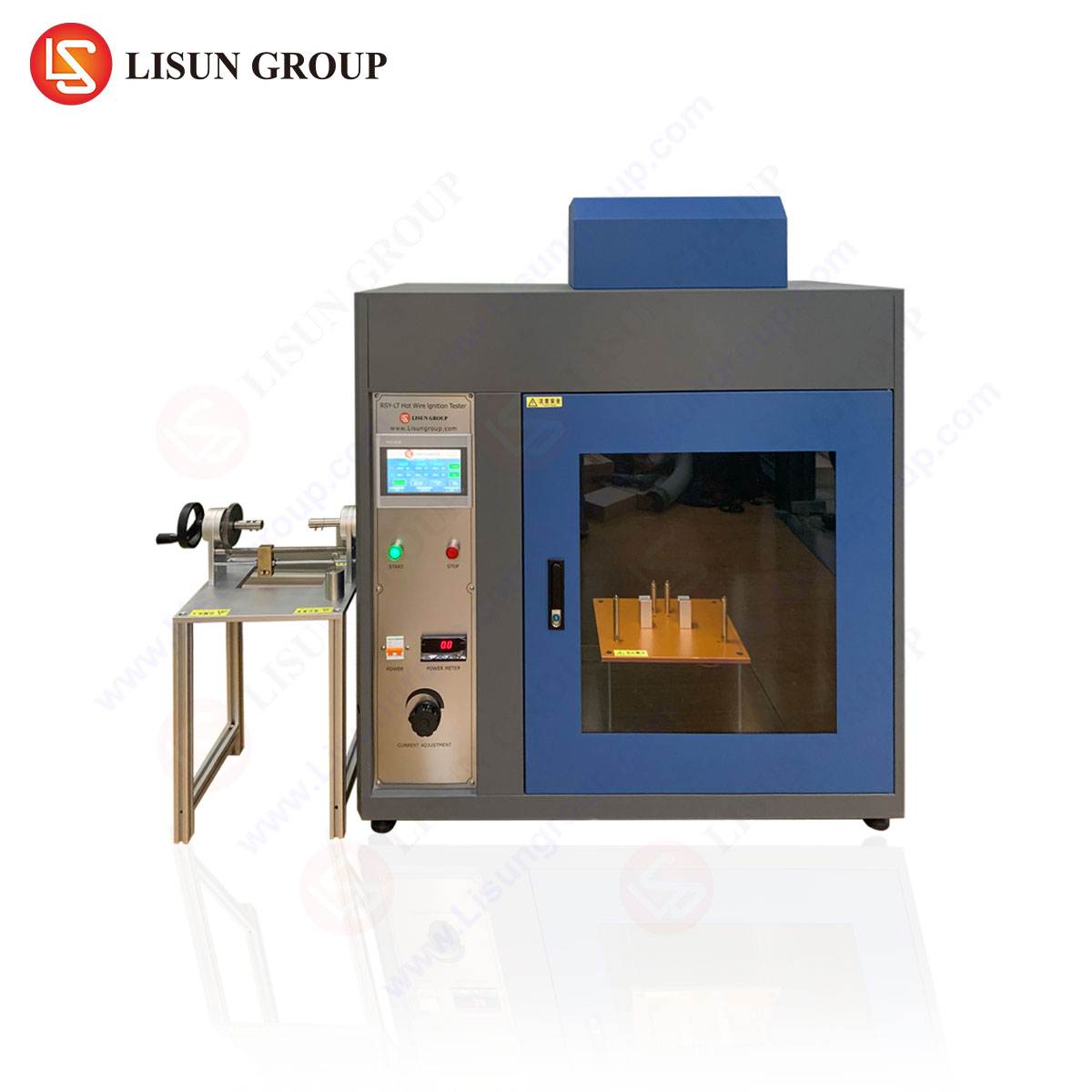
Architectural Overview of the LISUN RSY-LT Tester
The LISUN RSY-LT Hot Wire Ignition Tester embodies the engineering required to execute these standardized protocols with a high degree of accuracy and repeatability. Its architecture is designed to minimize operational variables and provide a controlled, observable environment for conducting tests. The system is typically housed within a robust metal frame, incorporating a ventilated test chamber to ensure the safe extraction of combustion products while maintaining a consistent airflow that does not disturb the test flame.
A central component is the specimen mounting stage, which allows for the precise and secure positioning of the test sample. Adjacent to this is the hot wire assembly, comprising a U-shaped or looped nickel-chromium wire held by two electrodes. These electrodes are connected to a programmable, low-voltage, high-current power supply. This supply is critical, as it must deliver a stable current with minimal ripple to ensure the test wire heats uniformly and consistently to the target temperature. The current is continuously monitored and controlled by a microprocessor-based system.
An integrated timing mechanism, often with millisecond accuracy, is automatically triggered upon application of current to the wire and ceases either upon ignition of the specimen or at the end of the pre-set heating period. If ignition occurs, a second timer measures the flame persistence duration after the current is automatically cut off. The entire apparatus is often complemented by a background of low-luminosity blue or black to enhance the visibility of flames, and a layer of surgical cotton is placed beneath the specimen to detect any flaming droplets that may cause secondary ignition.
Critical Specifications and Calibration Integrity
The validity of test data is contingent upon the equipment’s adherence to stringent specifications. For the RSY-LT model, these specifications are defined to meet the exacting requirements of the relevant standards.
Key specifications include:
- Test Current Range: Typically programmable from 0 to 150A, allowing for simulation of various overheating severities.
- Current Stability: High stability is paramount, with tolerances often within ±1% to prevent temperature fluctuations in the test wire.
- Timer Range: Two independent timers, one for ignition time (e.g., 0.1 to 999.9s) and one for flame duration (e.g., 0.1 to 999.9s), both with automatic start/stop functions.
- Hot Wire Composition: A standardized Ni-Cr wire, with a defined diameter (e.g., 0.5mm) and resistance per unit length.
- Test Voltage: A low voltage, often under 10V AC, is used for safety, supplied via a transformer isolated from the main power.
Calibration is a recurring necessity to maintain measurement integrity. This involves verifying the accuracy of the current measurement system against a traceable standard, often using a precision shunt resistor. The physical dimensions and resistance of the nickel-chromium wire must also be confirmed before each test series, as even minor deviations can significantly alter the heat flux applied to the specimen. The use of a pre-annealing procedure for new test wires, as stipulated in some standards, is another critical step to ensure consistent material properties and oxidation state before testing begins.
Application Spectrum Across Critical Industries
The application of hot wire flammability testing is vast, touching virtually every sector that utilizes electricity and insulating materials. Its role is to qualify materials for use in specific applications where an internal electrical fault is a plausible event.
In Household Appliances and Consumer Electronics, materials used in motor housings, internal supports for wiring, and enclosures for power supplies in devices like televisions, coffee makers, and chargers are routinely tested. A faulty connection on a switch or a degraded capacitor can become a hot wire ignition source.
The Automotive Electronics sector relies on this testing for components within the increasingly electrified vehicle architecture. Connectors, sensor housings, control module casings, and battery management system components must resist ignition from overheating in the harsh under-hood or in-cabin environments.
For Lighting Fixtures, particularly those using high-intensity or LED drivers where components can fail, the plastic housings and diffusers are evaluated to ensure they do not readily ignite from a failing ballast or driver component.
Telecommunications Equipment and Data Center Infrastructure use the test to validate the fire safety of materials in routers, servers, and power distribution units, where high current densities are common.
In Aerospace and Aviation, the stringent safety requirements demand that materials used in wire insulation, connector blocks, and electronic control units demonstrate high resistance to hot wire ignition to prevent in-flight incidents.
Medical Devices present a critical use case, where the failure of an internal component in a life-support or monitoring device must not lead to a fire that could endanger a patient in a clinical setting.
Finally, the test is fundamental for Electrical Components manufacturers, who use it to certify the safety of switches, sockets, connectors, and circuit breakers, ensuring that the insulating materials of the components themselves will not propagate a fire initiated by a poor connection.
Operational Workflow and Data Interpretation
A standardized operational sequence is followed to ensure reproducibility. The process begins with the conditioning of test specimens in a controlled atmosphere (e.g., 23°C ± 2°C and 50% ± 5% relative humidity) for a minimum period, typically 24 hours. The conditioned specimen is then mounted on the stage. The pre-measured and annealed test wire is formed into the specified shape and pressed against the specimen with a defined force.
The operator programs the test parameters—most critically, the test current and the maximum application time—into the controller. Upon initiation, the current is applied, and the primary timer starts. The operator observes the specimen for ignition, defined as the presence of a sustained flame. If ignition occurs, the current is automatically cut off, the ignition timer stops, and the flame persistence timer begins. This second timer stops once all flaming ceases. The test report documents the ignition time, flame persistence time, and notes regarding any burning droplets that ignite the cotton indicator.
Interpretation of results is directly tied to the material classification or the specific product standard. A common pass/fail criterion is that the flame must self-extinguish within a specified time (e.g., 30 seconds) after the removal of the hot wire, and that no flaming droplets are observed. Materials that pass are deemed to have a sufficient level of resistance to this specific ignition threat for their intended application.
Comparative Analysis of Tester Capabilities
When evaluating hot wire testers, several factors distinguish basic models from advanced systems like the RSY-LT. A primary differentiator is the sophistication of the power control system. Lower-end equipment may use simpler rheostat-based controls, which can be prone to current drift and are less precise. The RSY-LT utilizes closed-loop feedback control with a solid-state power regulator, ensuring the set current is maintained consistently throughout the test duration, which is critical for generating reliable and repeatable data.
Another advantage is the degree of automation. While manual timing and observation are permissible, automated timing triggered by a flame sensor reduces human error and subjectivity. Furthermore, features such as pre-programmed test routines for common standards, digital interfaces for data logging, and integrated safety interlocks (e.g., to prevent operation without the chamber door closed) enhance both the efficiency and safety of the testing process. The build quality, specifically the use of durable, non-corrosive materials for the test chamber and electrodes, ensures long-term calibration stability and reduces maintenance intervals, providing a lower total cost of ownership.
Integrating Test Data into Product Safety Engineering
The data derived from hot wire testing is not merely a compliance checkbox; it is a vital input into the product safety engineering lifecycle. By quantifying a material’s performance under fault conditions, designers can make informed decisions during the material selection phase. If a preferred material fails the test, engineers have several paths forward: they can select an alternative, more resistant material; they can redesign the component to increase the distance between potential hot spots and the material (a strategy known as “separation by distance”); or they can incorporate additional protective measures, such as thermal fuses or fire-retardant barriers.
This proactive integration of test data helps prevent costly redesigns late in the product development cycle and, more importantly, mitigates the risk of field failures that could lead to product recalls, property damage, or personal injury. In this context, the hot wire tester transitions from a quality control instrument to a fundamental tool for risk assessment and design validation.
Frequently Asked Questions (FAQ)
Q1: What is the critical distinction between a Glow-Wire Test and a Hot-Wire Test?
While both assess fire hazard, they simulate different failure modes. The Glow-Wire Test (e.g., IEC 60695-2-11) uses a heated element that is applied to the surface of a product or assembly to simulate overheating from a heat source like a faulty element. The Hot-Wire Test (e.g., IEC 60695-2-10) specifically simulates the effect of an overloaded electrical conductor or resistor igniting the insulating material that is in direct contact with it. The test apparatus, temperatures, and pass/fail criteria are distinct for each method.
Q2: How often should the current output of the tester be calibrated?
The calibration interval should be determined by the laboratory’s quality procedures, typically based on usage frequency and adherence to standards like ISO/IEC 17025. For high-usage labs, an annual calibration by an accredited service is common. It is also considered best practice to perform a daily or weekly verification check using a precision shunt resistor to monitor for any significant drift between formal calibrations.
Q3: Why is the pre-annealing of the nickel-chromium test wire necessary?
Pre-annealing involves heating the new test wire to a high temperature for a set period before its first use. This process serves two purposes: it stabilizes the crystalline structure of the metal alloy, ensuring consistent electrical resistance and heating behavior, and it promotes the formation of a stable surface oxide layer. This oxide layer prevents further rapid oxidation during the test, which could otherwise alter the wire’s resistance and the applied heat flux, leading to non-repeatable results.
Q4: Our material produces flaming droplets during the test. How should this be interpreted?
The production of flaming droplets is a critical observed phenomenon. Most standards, such as IEC 60695-2-13, explicitly state that the test fails if any burning droplets or particles fall from the specimen and ignite the surgical cotton indicator placed underneath. This is because such droplets can propagate fire to other combustible materials located away from the origin of the fault, significantly increasing the fire hazard. A material that exhibits this behavior is generally considered unsuitable for applications where it is positioned above other components or combustible surfaces.
Q5: Can the RSY-LT tester be used for materials beyond solid electrical insulations?
The primary design and standardization are for solid electrical insulating materials. However, the fundamental principle may be adapted for research and development purposes on other materials, provided the limitations are understood. For instance, testing very thin films or highly flexible materials may require special fixturing to ensure consistent contact with the hot wire. It is crucial to note that any deviation from the standardized test method invalidates the official certification value, and results should be treated as comparative internal data only.