


A Technical Overview of Shock Testing According to IEC 60068-2-27
Introduction to Mechanical Shock in Product Design
Mechanical shock represents a transient physical excitation characterized by a sudden, non-periodic transfer of energy to a product. In operational and handling environments, such events are ubiquitous and unpredictable, arising from phenomena such as casual mishandling, transportation over irregular terrain, abrupt operational forces, or minor collisions. The primary engineering concern with mechanical shock is not the immediate, gross structural failure, which is often self-evident, but the initiation of latent defects. These can manifest as fractured solder joints, dislodged internal components, cracked printed circuit boards (PCBs), or compromised hermetic seals. The objective of standardized shock testing, therefore, is to proactively identify these potential failure modes in a controlled laboratory setting before a product enters the marketplace. IEC 60068-2-27, “Environmental testing – Part 2-27: Tests – Test Ea and guidance: Shock,” provides the definitive international framework for this critical evaluation, establishing methodologies to verify a specimen’s structural and functional integrity under such transient conditions.
Fundamental Principles and Waveform Classifications
The core of IEC 60068-2-27 resides in its systematic approach to replicating and quantifying shock pulses. A shock pulse is defined by its time-history of acceleration, and the standard primarily deals with simple, classical pulses that can be precisely generated and reproduced in a laboratory. The shape, duration, and peak acceleration of the pulse are the critical parameters that define the severity of the test. The standard meticulously details three principal waveform types, each modeling a different physical interaction.
The half-sine pulse is the most frequently employed waveform, simulating an inelastic collision or a terminal velocity impact against a non-rigid surface. Its characteristic sinusoidal shape, defined by its peak acceleration (A) and pulse duration (D), delivers a high initial force that decays smoothly. This pulse is particularly effective for assessing the robustness of chassis-mounted components and overall product structures. The terminal peak sawtooth pulse, characterized by a near-linear rise to peak acceleration followed by an extremely rapid decay, models an elastic impact or a high-velocity collision where the stopping distance is very short. It is often specified for aerospace and military components where such high-G, short-duration events are anticipated. Finally, the trapezoidal pulse, with its rapid rise, sustained peak acceleration, and rapid decay, represents a compromise between the half-sine and sawtooth, offering a prolonged high-force interval. This is useful for simulating complex, multi-stage shock events.
The selection of the appropriate waveform is not arbitrary; it is a critical decision based on the product’s anticipated life-cycle profile. A household appliance dropped during relocation is best simulated with a half-sine pulse, while an automotive electronic control unit (ECU) experiencing a pothole impact might be tested with a shorter duration half-sine or a sawtooth pulse. The standard provides extensive guidance on this selection process, ensuring the test’s relevance.
Defining Test Severity and Rigorous Calibration Procedures
Test severity under IEC 60068-2-27 is quantified by a combination of the peak acceleration, the pulse duration, and the velocity change, which is the integral of the acceleration-time curve. A common severity level for commercial electronics might be 40g for 6 milliseconds (half-sine), whereas ruggedized industrial or automotive components may require testing at 100g for 3 milliseconds or higher. The standard provides standardized severity levels but also allows for the specification of custom test parameters derived from field data or more complex analysis.
A foundational tenet of the standard is the requirement for rigorous calibration of the test system. Without proper calibration, the test results are invalid and non-repeatable. The calibration process involves mounting a reference accelerometer of known, traceable accuracy to the fixture table or the specimen itself. During a trial shock pulse, the output of this transducer is recorded and analyzed. IEC 60068-2-27 stipulates strict tolerances for the generated pulse: the actual peak acceleration must be within ±10% of the specified value, the pulse duration within ±20%, and the velocity change within ±15%. Furthermore, the waveform must not exhibit excessive ripple or deviation from the ideal shape outside of the initial and final 10% of the pulse’s peak value. This meticulous attention to calibration ensures that every test, regardless of the laboratory in which it is performed, subjects the specimen to a known and reproducible mechanical environment.
Methodological Execution: Test Ea and Its Variants
The standard outlines several test procedures, collectively known as Test Ea. The most fundamental of these is the standard shock test, which involves subjecting the specimen to a specified number of shocks—typically three in each direction along each of three orthogonal axes. This comprehensive approach ensures that potential weaknesses are exposed regardless of the shock’s direction of incidence.
For a more severe assessment, the standard defines the bump test. This is essentially a high-frequency, low-severity shock test, often performed at a lower acceleration level but with a much higher number of applications, sometimes in the thousands. It is designed to simulate the cumulative effect of numerous minor shocks experienced during transit in a poorly suspended vehicle.
A critical variant is the functional shock test. In this procedure, the specimen is not merely a passive entity; it is powered up and performing its intended function throughout the shock event. The objective is to detect transient malfunctions, data corruption, or resets that a purely structural test would miss. This is paramount for devices like medical monitoring equipment, industrial programmable logic controllers (PLCs), or telecommunications routers, where a momentary lapse in function during a shock event could have significant consequences.
Finally, the crash hazard test is a specialized procedure designed to simulate the extreme shock conditions of a vehicular accident or other catastrophic event. It is characterized by very high acceleration levels and is typically reserved for safety-critical automotive electronics or components intended for deployment in hazardous environments.
The Role of the LISUN DT-60KG Drop Tester in Compliant Shock Testing
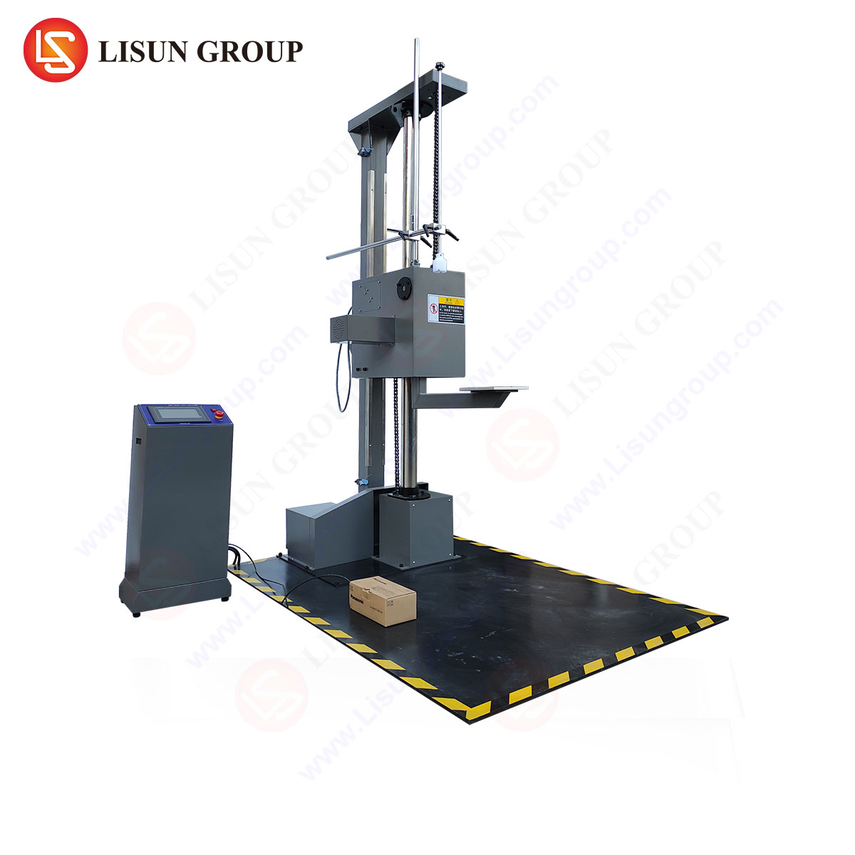
Achieving the precise and repeatable shock pulses mandated by IEC 60068-2-27 requires specialized, calibrated equipment. The LISUN DT-60KG Drop Tester represents a engineered solution designed specifically for this purpose, facilitating reliable and standardized shock testing across a diverse range of products. Its operational principle is based on a guided free-fall mechanism, where a drop table carrying the test specimen is raised to a pre-calculated height and released. The table then impacts a programmer—a specialized material or mechanical device placed on the base—which deforms in a controlled manner to generate the desired classical shock pulse.
The specifications of the DT-60KG are tailored to meet the demands of the standard. With a maximum load capacity of 60 kg, it accommodates a wide array of products, from small electrical components like switches and sockets to larger assemblies such as office equipment or automotive ECUs. Its adjustable drop height allows for the precise control of impact velocity, a key factor in determining the peak acceleration of the resulting shock pulse. The system’s programmability enables the execution of complex test sequences, including the specified number of shocks per axis, and its integrated safety features, such as mechanical locking mechanisms, ensure operator protection during testing.
The competitive advantage of a system like the DT-60KG lies in its calibration stability and waveform fidelity. By utilizing interchangeable programmers of varying materials and stiffness, the tester can be configured to generate highly accurate half-sine, sawtooth, or trapezoidal pulses. This versatility makes it an indispensable tool for manufacturers in the lighting fixture industry testing the resilience of bulb filaments and housing, or for producers of consumer electronics validating the durability of handheld devices against drop impacts. The data acquisition system, often integrated or compatible with the tester, provides the necessary documentation to prove compliance with the standard’s stringent calibration tolerances.
Industry-Specific Applications and Failure Mode Analysis
The application of IEC 60068-2-27 is vast, with test parameters finely tuned to the unique stresses of each sector.
In Automotive Electronics, an engine control module (ECM) is subjected to high-G, short-duration shocks to simulate pothole strikes. A typical test might involve a 50g, 3ms half-sine pulse. Failure modes detected can include cracked ceramic substrates on power resistors or broken pins on large-scale integrated circuits.
Aerospace and Aviation Components, such as an inertial navigation unit, must withstand the shocks of landing gear deployment and runway contact. Testing often employs sawtooth pulses of 20g over 11ms. The analysis focuses on the integrity of crystal oscillators and the permanence of connector mating.
For Medical Devices, a portable patient monitor undergoes functional shock testing. A 15g, 11ms half-sine pulse might be applied while the device is actively acquiring and displaying vital signs. The test aims to uncover any transient display blanking, data logging errors, or unintended system reboots that could compromise patient safety.
Telecommunications Equipment, including a base station amplifier, is tested for robustness against shocks during shipping and handling. A series of 25g, 6ms shocks can reveal weaknesses in the solder joints connecting large heat sinks to PCBs, a common point of failure in such modules.
Household Appliances, like a robotic vacuum cleaner, are tested to simulate being dropped a short distance during stairs or being knocked over. A 40g, 6ms half-sine pulse, easily generated by a system like the LISUN DT-60KG, can identify failures in plastic housing clips, battery connector integrity, or the mounting of the drive motor.
Integrating Shock Testing into a Broader Reliability Engineering Framework
Shock testing according to IEC 60068-2-27 should not be viewed as a standalone event, but rather as an integral component of a comprehensive product validation strategy. Its findings are most powerful when correlated with other environmental and mechanical tests. For instance, a product that passes a shock test in a benign laboratory environment might fail the same test after being subjected to a temperature-humidity cycle per IEC 60068-2-30, as the thermal stress can embrittle adhesives or weaken solder.
Furthermore, the data derived from shock testing is invaluable for Finite Element Analysis (FEA) model validation. By comparing the simulated dynamic response of a virtual product model with the actual acceleration data measured during a physical test on a DT-60KG, engineers can refine their models to achieve a high degree of predictive accuracy. This synergy between physical testing and simulation accelerates the design iteration process, allowing for weaknesses to be identified and remedied early in the development cycle, thereby reducing both cost and time-to-market.
Ultimately, the disciplined application of IEC 60068-2-27, supported by capable equipment, transforms shock testing from a simple pass/fail gate into a rich source of engineering intelligence. It provides empirical evidence of a product’s durability, informs design improvements, and builds a foundation of reliability that supports brand reputation and user safety across global markets.
Frequently Asked Questions (FAQ)
Q1: How is the appropriate test severity (peak acceleration and pulse duration) selected for a new product?
The selection is based on the product’s life-cycle profile. This involves analyzing the expected transportation methods (e.g., parcel carrier handling), end-use environment (e.g., vehicle-mounted, stationary consumer use), and any relevant industry-specific standards. Historical field failure data from previous generations of the product and standards like ISTA for transportation can also provide guidance. For novel products, an iterative approach, starting with a conservative estimate and adjusting based on test outcomes, may be necessary.
Q2: Can the LISUN DT-60KG Drop Tester be used for both half-sine and sawtooth shock pulses?
Yes, the DT-60KG is designed to generate different classical shock pulses through the use of interchangeable programmers. A programmer made of a plastically deforming material, such as lead or a specific polymer, is used to produce a half-sine pulse. To generate a terminal peak sawtooth pulse, a different type of programmer, often involving a pneumatic or hydraulic damper mechanism, is employed. The system’s versatility is a key feature for laboratories testing products against multiple standards or with varying shock requirements.
Q3: What is the significance of testing along three orthogonal axes?
Components and assemblies are not mechanically isotropic; their resonant frequencies and structural weaknesses are highly dependent on the direction of the applied force. A product may withstand a shock in one direction but fail catastrophically in another due to the orientation of a heavy component, like a transformer, or the layout of a PCB. Applying shocks in three axes (typically denoted X, Y, and Z) ensures a comprehensive assessment of the product’s structural integrity from all possible angles of incidence.
Q4: Why is functional testing during a shock event so critical for devices like medical or industrial control equipment?
A purely mechanical shock test only verifies that the product does not suffer physical damage. However, a shock can cause momentary electrical discontinuities, voltage sags, or signal noise that can trigger a software fault, a system reset, or corrupted data transmission without causing any permanent physical damage. For a life-support device or an industrial controller, this transient functional interruption is a critical failure. Functional shock testing is therefore essential to verify operational continuity under dynamic stress.