


A Technical Guide to IEC 60947-1 Compliance for Low-Voltage Switchgear and Controlgear
Abstract
The international standard IEC 60947-1 establishes the foundational requirements for low-voltage switchgear and controlgear assemblies. Compliance is not merely a regulatory hurdle but a fundamental prerequisite for ensuring operational safety, reliability, and global market access for a vast range of electrical equipment. This document provides a comprehensive analysis of the standard’s core tenets, with particular emphasis on the verification of performance under abnormal conditions, such as arc fault management. It further explores the critical role of specialized testing apparatus, including high-current arc ignition test systems, in validating compliance with these stringent safety protocols.
Foundational Principles and Scope of IEC 60947-1
IEC 60947-1, titled “Low-voltage switchgear and controlgear – Part 1: General rules,” serves as the overarching framework for a family of product-specific standards (e.g., IEC 60947-2 for circuit-breakers, IEC 60947-3 for switches, etc.). Its primary objective is to define the general characteristics, behavior, and verification methods for equipment used to control, protect, and isolate electrical circuits operating at voltages up to 1000 V AC or 1500 V DC. The standard’s scope is intentionally broad, encompassing devices found in industrial control systems, power distribution networks, and integrated within end-products like household appliances, automotive electronics, and telecommunications equipment. It addresses a multitude of parameters including constructional requirements, performance characteristics under normal and abnormal load conditions, dielectric properties, temperature rise limits, and clearances and creepage distances. A fundamental principle underpinning the standard is the concept of “type testing,” whereby a representative sample of a product family is subjected to a rigorous series of tests to certify that the entire manufacturing series conforms to the stipulated safety and performance benchmarks.
Constructional Requirements for Mechanical and Electrical Integrity
The mechanical and electrical integrity of switchgear and controlgear is paramount to its safe operation over its intended lifespan. IEC 60947-1 mandates stringent constructional requirements to mitigate risks associated with mechanical failure, electric shock, and fire. These requirements are meticulously detailed and cover the properties of materials used, the robustness of enclosures, and the security of electrical connections. Key aspects include the provision of adequate mechanical strength to withstand operational stresses encountered in environments ranging from industrial control panels to aerospace components. Enclosures must provide a defined degree of protection against the ingress of solid foreign objects and moisture, as classified by the IP (Ingress Protection) code. Furthermore, the standard specifies requirements for the durability of insulating materials, which must retain their dielectric and mechanical properties when exposed to factors like heat, humidity, and ultraviolet radiation. The integrity of terminations for incoming and outgoing conductors is also critical, ensuring that connections remain secure under the influence of electrodynamic forces generated by high-current faults, thereby preventing hot spots and potential ignition sources.
Verification of Dielectric Properties and Insulation Coordination
Insulation coordination is a systematic approach to ensuring that the insulation strength of equipment is commensurate with the overvoltages that can appear in the system, thereby preventing dielectric failure. IEC 60947-1 outlines specific test procedures to verify the dielectric properties of equipment. The primary test is the impulse withstand voltage test, which subjects the insulation to a standardized voltage surge simulating transient overvoltages, such as those caused by lightning strikes or switching operations in electrical distribution systems. Following this, a power-frequency withstand voltage test (typically at 50 Hz or 60 Hz) is applied to verify the insulation’s strength under steady-state overvoltage conditions. These tests are conducted between poles of opposite polarity, between live parts and the frame, and across open contacts. The test voltages are carefully selected based on the equipment’s rated insulation voltage and its intended overvoltage category (e.g., Category IV for equipment at the origin of the installation, like electricity meters). Successful completion of these tests demonstrates that the clearances (air distances) and creepage distances (surface paths) are sufficient to prevent flashover and tracking, which is especially critical in medical devices and telecommunications equipment where operational continuity is essential.
Thermal Performance and Temperature-Rise Validation
The evaluation of thermal performance under normal operating conditions is a critical aspect of the standard. Excessive temperature rise can lead to premature aging of insulating materials, oxidation of contacts, and ultimately, component failure. IEC 60947-1 specifies maximum allowable temperature rises for various components—such as terminals, contacts, and coils—above a reference ambient temperature, usually 40°C. The temperature-rise test is a type test performed by applying the rated operational current (Ie) to the main circuit and the rated operational voltage to the control circuits until thermal equilibrium is reached, a process that can take several hours. Measurements are taken using thermocouples or resistance methods at predefined points. Compliance ensures that the design provides adequate heat dissipation through proper sizing of conductors, use of appropriate contact materials, and effective design of the enclosure or assembly. This is particularly important for equipment like industrial motor controllers, lighting fixture ballasts, and power supplies for office equipment, where sustained operation is required.
Assessing Performance Under Abnormal Current Conditions
Beyond normal operation, switchgear and controlgear must safely interrupt or withstand abnormal currents. This includes verifying the short-circuit withstand strength of mechanical switching devices and the making and breaking capacities of protective devices like circuit-breakers. For assemblies not intended to interrupt fault currents, such as busbars or distribution boards, the standard requires short-time withstand current (Icw) testing. This test demonstrates that the assembly can endure the thermal and electrodynamic stresses of a short-circuit current for a specified duration (e.g., 1 second) without catastrophic failure. The electrodynamic forces are proportional to the square of the peak current, imposing immense mechanical stress on conductors and supports. Concurrently, the I²t value determines the thermal stress. Validation in this area is non-negotiable for equipment used in cable and wiring systems, ensuring that a downstream fault does not cause an upstream fire or explosion.
The Critical Role of Arc Fault Testing in Equipment Safety
One of the most severe abnormal conditions an electrical assembly can face is an internal arc fault. An arc fault occurs when an electric current deviates from its intended path, traveling through the air between conductors or to ground, resulting in a sustained plasma discharge of immense energy. The consequences include extreme heat, intense pressure waves, and the ejection of molten metal and hot gases. IEC 60947-1, in conjunction with standards like IEC 61641 (guidance for testing under conditions of arcing due to internal fault), addresses the need to contain the effects of an internal arc to protect personnel and adjacent equipment. The objective of arc fault testing is not to prevent the arc—which can be initiated by insulation degradation, contamination, or accidental contact—but to verify that the enclosure can withstand the internal pressure and channel the expelled gases in a controlled manner away from operational areas. This is a critical safety consideration for switchgear installed in accessible locations, such as within manufacturing plants or commercial buildings.
Utilizing the HCAI-2 High Current Arc Ignition Test System for Compliance Verification
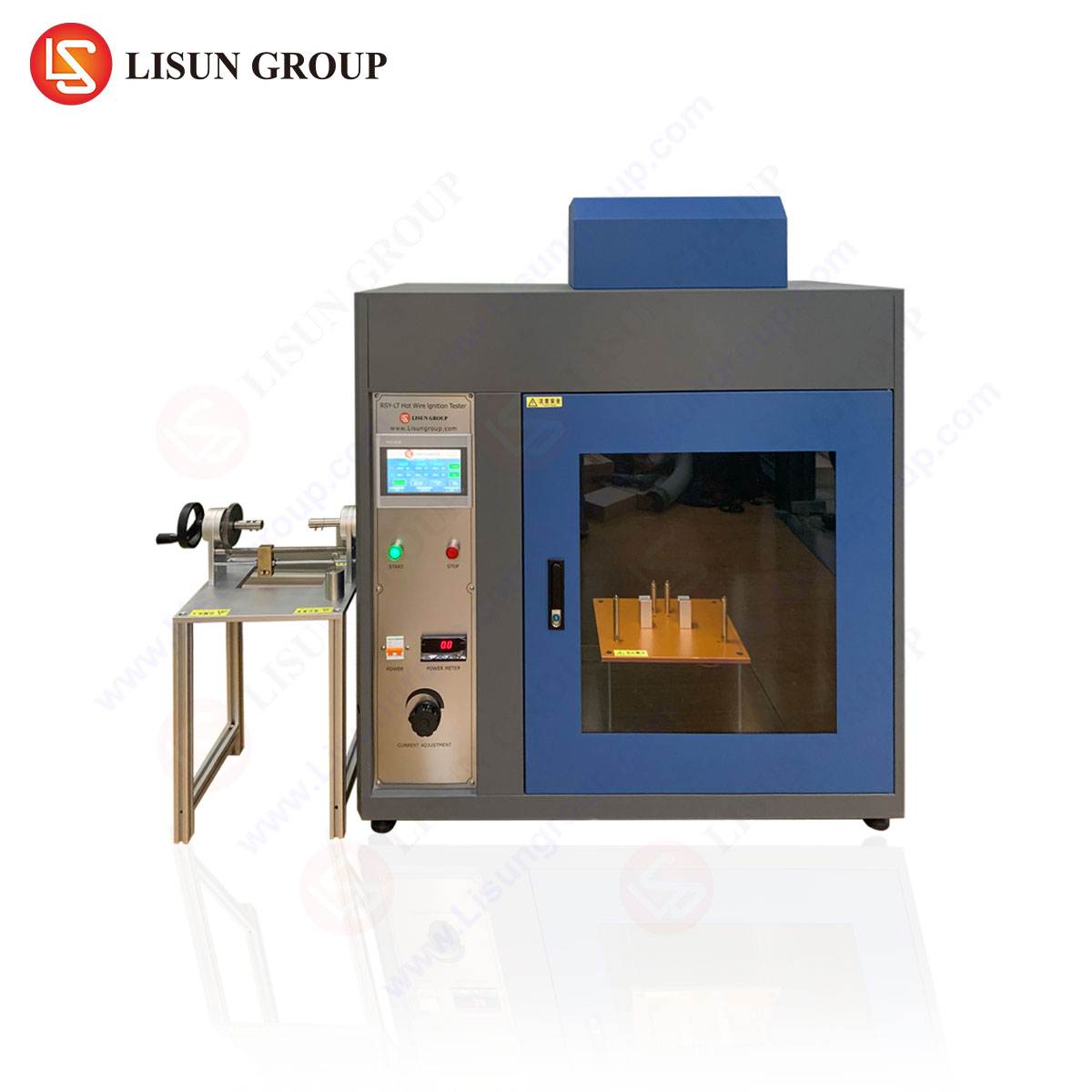
Verifying an assembly’s resilience to internal arc faults requires specialized, high-fidelity test equipment capable of generating and controlling a high-energy electrical arc under laboratory conditions. The LISUN HCAI-2 High Current Arc Ignition Test System is engineered specifically for this purpose, enabling manufacturers to validate their designs against the stringent requirements of IEC 60947-1 and related arc fault standards. The system is designed to simulate realistic arc fault conditions by generating a low-voltage, high-current arc within a test specimen.
The testing principle involves establishing a controlled arc between electrodes inside the equipment under test (EUT) using a high-current power supply. The HCAI-2 system precisely regulates the prospective short-circuit current (e.g., up to 10 kA, 20 kA, or higher, depending on configuration) and the duration of the arc. Key specifications of such a system typically include a programmable current source, a remote ignition unit (often using a wire fuse or a carbon rod method to initiate the arc), and comprehensive data acquisition to record current, voltage, and pressure transients during the event. Industry use cases are extensive, applying to manufacturers of motor control centers (MCCs), power distribution boards, and controlgear assemblies for the renewable energy and aerospace sectors. The competitive advantage of a system like the HCAI-2 lies in its precision, repeatability, and safety features. It allows engineers to gather empirical data on arc behavior, pressure buildup, and the effectiveness of arc quenching chambers or pressure relief flaps, facilitating iterative design improvements that enhance passive safety without relying solely on active protection schemes.
Interpretation of Test Results and Certification Logistics
Upon completion of the required type tests, the resulting data must be meticulously analyzed against the acceptance criteria defined in IEC 60947-1. For dielectric tests, the criterion is typically the absence of flashover or breakdown. For temperature-rise tests, measured values must not exceed the tabulated limits. For arc fault tests, success is often defined by the integrity of the enclosure (no fragmentation of doors or panels), the absence of ignition of indicator paper placed around the assembly, and the safe direction of hot gases. Once a product successfully passes all applicable tests, a recognized certification body (such as UL, TÜV, or Intertek) can issue a certificate of conformity. This certification is the formal evidence that the product meets the standard’s requirements and is a critical document for market access. It is important to note that certification is typically valid for the specific type tested; significant design changes may necessitate re-testing or a supplemental investigation.
Integration of Compliance into the Product Development Lifecycle
Achieving compliance should not be an endpoint but an integrated process throughout the product development lifecycle. From the initial concept and design phases, engineers must incorporate the requirements of IEC 60947-1. This includes material selection, geometric design for adequate clearances, thermal modeling for heat dissipation, and mechanical simulations for short-circuit strength. Utilizing advanced testing tools like the HCAI-2 early in the prototyping phase allows for the identification and mitigation of potential arc fault vulnerabilities before finalizing the design. This proactive approach, known as Design for Compliance (DfC), reduces the risk of costly redesigns and delays during the final certification stage. It fosters a culture of safety-by-design, which is essential for manufacturers of electrical components, automotive electronics, and consumer electronics who operate in highly competitive and regulated global markets.
Frequently Asked Questions (FAQ)
Q1: What is the primary difference between the short-circuit withstand test and an arc fault test?
The short-circuit withstand test (Icw) verifies that an assembly can withstand the magnetic and thermal stresses of a high-current fault without an arc being intentionally initiated inside the enclosure. The current is passed through the main conductors. In contrast, an arc fault test intentionally creates a plasma arc inside the enclosure to evaluate its ability to contain the explosion, pressure, and heat, and to direct hot gases safely away.
Q2: For which types of products is arc fault testing according to IEC 60947-1 mandatory?
Arc fault testing is not universally mandatory for all equipment under IEC 60947-1. Its application is typically specified by the product-specific part of the standard or is required by the manufacturer’s declared operational performance or by the end-user’s specifications. It is most common for enclosed low-voltage switchgear and controlgear assemblies intended for installation in areas where personnel may be present during operation.
Q3: How does the HCAI-2 system ensure consistent and repeatable arc ignition?
Systems like the HCAI-2 use a standardized ignition method, such as a fusible wire or a carbon fiber thread stretched between the electrodes. A controlled current pulse vaporizes this wire, creating a conductive plasma path that initiates the main power arc. This method ensures that the arc’s point of initiation and initial conditions are consistent across multiple tests, which is crucial for obtaining comparable and reliable data.
Q4: Can the HCAI-2 system be configured for different international supply voltages and frequencies?
Yes, high-current test systems are typically designed with flexibility in mind. The primary power input and the high-current transformer can be engineered to accommodate various standard supply voltages (e.g., 380V, 480V) and frequencies (50 Hz or 60 Hz) to suit different laboratory infrastructures around the world.
Q5: What data is typically recorded during an arc fault test with the HCAI-2?
A comprehensive test will record several key parameters: the prospective short-circuit current, the actual arc current and voltage waveforms over time, the internal pressure transient within the enclosure, and high-speed video footage of the event. This data is essential for understanding the arc’s energy, the pressure dynamics, and the overall performance of the enclosure.