


An Analytical Framework for the Glow-Wire Ignition Test According to IEC60695-2-20
The proliferation of electrical and electronic equipment across diverse sectors has irrevocably increased the density of potential ignition sources within operational environments. Mitigating the risk of fire, particularly from malfunctioning components that may overheat, is a paramount objective for designers, manufacturers, and regulatory bodies worldwide. A critical methodology for assessing this risk is the simulation of thermal stress caused by overloaded or poorly connected components. The International Electrotechnical Commission (IEC) standard 60695-2-20, “Glow-wire flammability test method for materials,” provides a rigorous and internationally recognized procedure to evaluate the ignition susceptibility and flame-spread characteristics of solid electrical insulating materials.
This standardized test does not seek to replicate every conceivable real-world fire scenario. Instead, it establishes a reproducible and severe conditional simulation to determine the behaviour of a material when subjected to a specific thermal stress in the form of a glowing element. The data derived from this procedure are instrumental in material selection, quality control, and the overarching goal of enhancing product safety and reliability.
Fundamental Principles of the Glow-Wire Test Methodology
The core principle underpinning IEC60695-2-20 is the application of a heated element—the glow-wire—to a test specimen under controlled laboratory conditions. The glow-wire, constructed from a specific nickel/chromium alloy with a standardized dimensions, is heated electrically to a predetermined temperature, which is verified using a calibrated type K thermocouple. This temperature is a key test parameter and is selected based on the material’s intended application and the relevant end-product safety standard.
The test specimen, conditioned to a specified atmospheric environment, is then subjected to a force from the glow-wire for a defined period, typically 30 seconds. The entire process is monitored for several critical phenomena. The primary observations include whether the specimen ignites, the duration of any subsequent flames, and whether the flames extinguish within a specified time after the removal of the glow-wire. Additional observations may include the production of burning or molten droplets that could ignite a layer of tissue paper positioned below the specimen, simulating the ignition of surrounding materials.
The pass/fail criteria, defined in the end-product standards (such as the IEC 60335 series for household appliances or IEC 60950 for IT equipment), are generally based on these observations. For instance, a common criterion is that the specimen must not ignite, or if it does, flames must self-extinguish within a set period after the removal of the glow-wire, and no dripping of particles ignites the tissue paper. This quantitative assessment provides a clear, comparative basis for material performance.
Operational Mechanics of the RSY-LT Hot Wire Ignition Tester
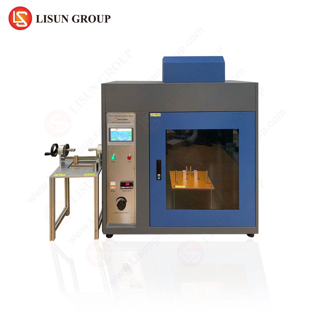
To perform the IEC60695-2-20 test with the requisite precision and repeatability, specialized apparatus is mandatory. The LISUN RSY-LT Hot Wire Ignition Tester embodies an engineered solution that integrates the standard’s requirements into a reliable and user-friendly platform. Its design focuses on ensuring accurate temperature control, consistent application of force, and operator safety.
The testing principle of the RSY-LT begins with the secure mounting of the glow-wire probe within the apparatus. The operator sets the desired test temperature via a digital controller. A closed-loop feedback system, utilizing the integrated thermocouple, maintains the glow-wire tip at the target temperature with a high degree of stability, a critical factor for test reproducibility. The test specimen is clamped in a fixture that can be moved horizontally to bring it into contact with the stationary glow-wire. A precision weight-and-lever system applies the standard-required force of 1.0 N ± 0.2 N to the specimen against the glow-wire. The apparatus includes a specimen holder that can be rotated to test different areas of the same sample, thereby maximizing data yield from a single specimen.
A key operational feature is the integrated timing mechanism. The instrument automatically times the 30-second application period and, if ignition occurs, continues to time the duration of flaming. An extinguish indicator alerts the operator when flames have ceased. The entire test chamber is constructed from heat-resistant and flame-retardant materials and is often equipped with an exhaust system to safely remove potentially toxic pyrolysis products, aligning with laboratory safety protocols.
Specifications of the LISUN RSY-LT Hot Wire Ignition Tester:
- Temperature Control Range: 100 °C to 1000 °C (continuously adjustable).
- Temperature Stability: ± 2 °C at 960 °C.
- Glow-Wire Heating Current: 0 to 150 A (AC).
- Test Duration: 0 to 99.99 seconds (digital timer, automatically controlled).
- Application Force: 1.0 N ± 0.2 N (applied via a calibrated weight system).
- Timing for Flaming: 0 to 99.99 seconds (automatic recording upon ignition).
- Test Specimen Size: Maximum thickness of 10 mm, with standard clamping for various forms.
- Safety Features: Over-temperature protection, emergency stop button, and ventilated test chamber.
Material Response and Failure Mode Analysis
Interpreting the results of a glow-wire test extends beyond a simple pass/fail determination. A detailed analysis of the material’s response provides invaluable insights for engineering and development teams. When a material is subjected to the thermal stress of the glow-wire, several distinct failure modes can be observed, each with implications for product design.
One common response is material ignition followed by sustained flaming. This indicates a high propensity for the fire to propagate and would typically constitute a failure. Conversely, a material may ignite but the flames may self-extinguish within the permitted time (e.g., 30 seconds), demonstrating a degree of flame-retardant capability. Another critical failure mode involves the production of incandescent or flaming droplets. While the main specimen may not sustain a fire, these droplets can act as secondary ignition sources for other components or materials, such as wire harnesses or dust accumulations. This is particularly relevant in vertically stacked equipment like industrial control cabinets or telecommunications servers.
Some thermoplastic materials may not ignite but will melt and recede extensively from the glow-wire, a phenomenon known as “non-ignition with hole formation.” While this may not constitute a direct ignition failure, it can expose internal live parts, leading to a risk of electric shock or short-circuit in a real-world failure. The depth and morphology of the char or melt zone, often measured post-test, can also be a comparative metric for material thermal endurance. Understanding these nuanced responses allows engineers to select materials not just based on a test certificate, but on a comprehensive understanding of their failure characteristics under thermal abuse.
Industry-Specific Applications and Risk Mitigation
The applicability of IEC60695-2-20 testing spans a vast spectrum of industries where electrical energy is converted, controlled, or transmitted. In each sector, the test addresses unique failure scenarios.
Automotive Electronics: The confined, vibration-prone, and thermally challenging environment of a vehicle necessitates components that resist ignition. Connectors, sensor housings, and control unit casings are tested to ensure that a short-circuit or overload in a nearby wire or component will not lead to a fire. The use of the RSY-LT tester allows automotive suppliers to validate materials for components like battery management systems and infotainment units against stringent OEM specifications.
Household Appliances and Electrical Components: Switches, sockets, terminal blocks, and the internal housings of appliances like coffee makers, power supplies, and motor controllers are common applications. A loose connection in a switch can generate persistent heat, simulating the conditions of the glow-wire test. Ensuring that the surrounding plastic material does not ignite is critical for preventing a household fire.
Lighting Fixtures and Consumer Electronics: Modern LED drivers, power adapters for laptops, and the internal structures of lighting fixtures often operate at high temperatures. The glow-wire test assesses the materials used in lamp holders, transformer bobbins, and device enclosures to prevent fire initiation from a faulty ballast or power supply. The precision temperature control of the RSY-LT is essential for testing the high-temperature thermoplastics often used in these applications.
Medical Devices and Aerospace Components: In these high-reliability sectors, failure is not an option. Ventilators, patient monitors, and avionics equipment must maintain integrity even under fault conditions. The test is used to qualify materials for internal structures, connector housings, and insulation parts, ensuring that a single point of electrical failure does not cascade into a catastrophic event.
Competitive Advantages of Automated Glow-Wire Test Systems
Transitioning from a rudimentary test setup to a fully integrated system like the LISUN RSY-LT confers significant advantages in terms of data integrity, operational efficiency, and compliance assurance. The primary competitive differentiators lie in the areas of measurement precision and process automation.
A key advantage is the system’s calibrated temperature control loop. Inconsistent glow-wire temperature is a major source of inter-laboratory variation. The RSY-LT’s ability to maintain the setpoint temperature within a tight tolerance (±2°C) ensures that test results are reproducible and directly comparable over time and across different facilities. This level of control is difficult to achieve with less sophisticated apparatus.
Furthermore, the automation of timing and observation functions reduces operator-induced error. Manual timing of flame duration is subjective and can lead to inaccuracies. The automated timing function of the RSY-LT, triggered by the photoelectric sensor for flame detection, provides an objective and precise measurement of after-flame time (tf) and after-glow time (ti). The integrated data logging capabilities allow for the secure storage of test parameters and results, which is invaluable for quality audits and traceability requirements mandated by standards such as ISO/IEC 17025 for testing laboratories.
The robust mechanical design, with its precise force application system and stable specimen holder, ensures that the mechanical aspects of the test are consistently applied. This holistic approach to standard compliance—encompassing thermal, temporal, and mechanical parameters—makes automated systems a superior choice for laboratories focused on generating reliable, defensible, and high-quality test data for critical safety evaluations.
Frequently Asked Questions (FAQ)
Q1: How is the appropriate test temperature (GWIT) for a material determined?
The Glow-Wire Ignition Temperature (GWIT) is determined through a series of tests at different temperatures. The GWIT is defined as the temperature 25 K (or 50 K for some materials) above the maximum test temperature at which the material does not ignite, or if it does, flames extinguish within 5 seconds and no dripping occurs. The specific temperature requirements are ultimately dictated by the end-product standard. For example, a standard for a household switch might mandate a GWIT of 750°C.
Q2: What is the critical distinction between the GWT (Glow-Wire Test) and the GWFI (Glow-Wire Flammability Index)?
The GWT is the procedure itself. The GWFI is a specific result derived from it. The Glow-Wire Flammability Index (GWFI) is the highest temperature at which a material can be tested and still pass three consecutive tests without meeting the failure criteria (e.g., flames persisting beyond 30 seconds or ignition of the tissue paper by droplets). It represents a material’s ability to not spread fire under the test conditions. A material is often classified by its GWFI value.
Q3: Why is the 1.0 N application force so critical in the RSY-LT tester?
The application force directly influences the thermal contact resistance between the glow-wire and the test specimen. An inconsistent or incorrect force can lead to significant variations in heat transfer, causing a specimen to appear more or less resistant to ignition than it truly is. The calibrated weight system in the RSY-LT ensures this force is applied uniformly for every test, which is a fundamental requirement for achieving reproducible and comparable results as per the standard.
Q4: Can the RSY-LT tester be used for testing non-standard or oddly shaped components?
While the standard specifies a flat specimen, the principle can be applied to component testing as specified in other standards like IEC 60695-2-11. The RSY-LT’s versatile specimen clamping system can often accommodate small components like connectors or switches. However, the test parameters and pass/fail criteria for such component tests are defined in the specific end-product standard, not in IEC60695-2-20 itself. The apparatus provides the means to perform the test, but the test plan must be engineered accordingly.