The Role of IEC Standards in Defining Fire Resistant Cable Performance
The integrity of electrical circuits during a fire event is a critical safety consideration across a multitude of industries. Fire resistant cables are engineered to maintain circuit integrity for a specified period under defined fire conditions and mechanical shock, allowing for the continued operation of essential safety systems such as emergency lighting, fire alarms, and ventilation controls. The International Electrotechnical Commission (IEC) provides the global benchmark for evaluating and certifying the performance of these vital components. The IEC 60331 series of standards, specifically, establishes the rigorous test methods for cables designed to maintain electrical functionality under fire conditions.
Understanding these standards is paramount for engineers, specifiers, and manufacturers involved in the design and production of electrical systems for buildings, industrial plants, and transportation infrastructure. Compliance with IEC 60331 is not merely a regulatory hurdle; it is a fundamental aspect of risk mitigation and life safety strategy. The standard delineates precise procedures for exposing cable samples to high temperatures, typically in the range of 750°C to 950°C, while simultaneously subjecting them to a rated voltage to verify continued operation. This objective, performance-based framework ensures a consistent and reliable assessment of cable fire resistance, independent of geographical market or manufacturer claims.
Deconstructing the IEC 60331 Test Methodology
The IEC 60331 standard is subdivided into several parts, each addressing specific test conditions and cable applications. The core objective remains consistent: to assess the ability of a cable to continue functioning while exposed to fire. The primary divisions include tests for cables with a rated voltage not exceeding 0.6/1.0 kV and those for higher voltages, and further categorizations based on installation methods.
A fundamental test outlined in the standard involves mounting a cable sample in a specialized furnace. The sample is then heated to a designated temperature, such as 750°C ±40°C for a standard test, for a duration specified by the cable’s performance category (e.g., 90, 120, or 180 minutes). Throughout this exposure, the cable must carry its rated current. A nominal voltage is applied to the conductor under test, and the integrity of the circuit is monitored. Failure is defined as the operation of the fuse or circuit breaker due to a short-circuit caused by the degradation of the insulation, or the cessation of current flow due to an open circuit. The standard meticulously defines the furnace characteristics, temperature profiling, and sample preparation to ensure reproducibility of results across different testing laboratories.
The mechanical robustness of a fire resistant cable during a fire is another critical parameter addressed in parts of the IEC 60331 series. In real-world scenarios, a fire can lead to structural collapse, causing cables to be impacted by falling debris or subjected to significant mechanical stress. The standard includes provisions for applying a mechanical shock to the cable during the fire test, simulating such conditions and verifying that the cable can withstand both thermal and physical assault without losing circuit integrity.
Critical Apparatus for Compliance: The RSB-WC Wire Cable Flame Tester
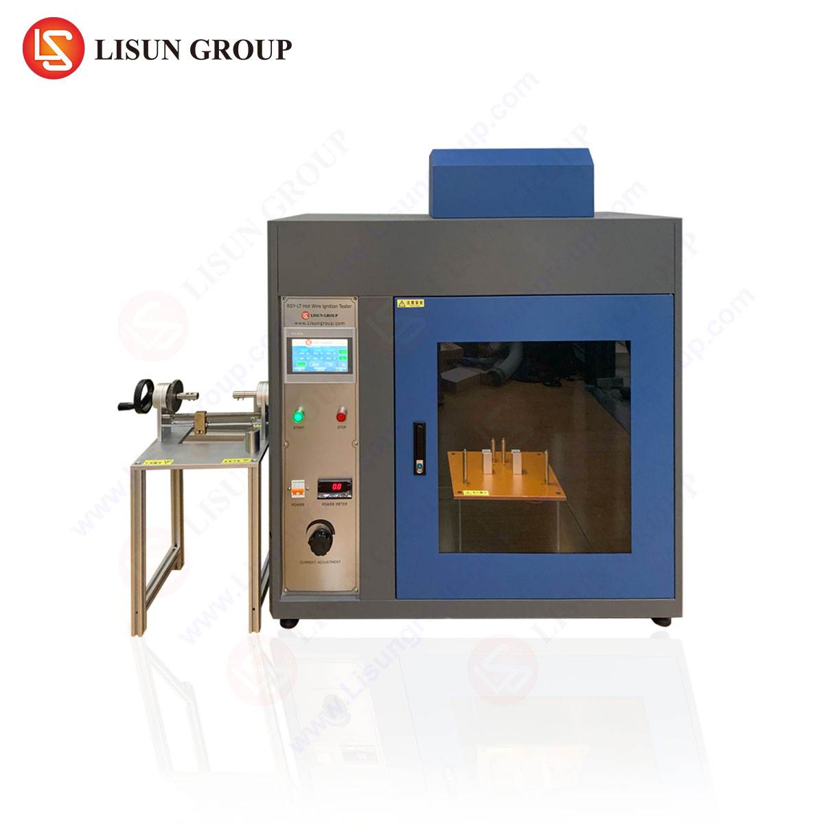
Achieving and verifying compliance with standards like IEC 60331 requires sophisticated and precisely calibrated testing apparatus. Instruments such as the LISUN RSB-WC Wire Cable Flame Tester are engineered specifically to meet these demanding requirements. This apparatus is designed to conduct flame tests on wires and cables, providing critical data on their flame retardancy and fire resistance properties, which are foundational to meeting IEC and other international standards.
The RSB-WC operates on the principle of controlled flame application and observation. A specified propane burner is used to apply a calibrated flame to a mounted cable sample at a predetermined angle and distance. The test measures the extent of flame spread along the sample after the ignition source is removed, as well as the duration of after-flame and after-glow. Key specifications of the RSB-WC that ensure alignment with standard test methods include a combustion chamber constructed from stainless steel with heat-resistant glass observation windows, a standardized propane flow meter for precise flame control, and an automated test sequencer for consistent timing of flame application and post-ignition observation periods. The inclusion of a calibrated methane or propane burner with a specific heat output, often 1kW or other values as per the referenced standard, is a critical component for generating reproducible and comparable results.
The data generated by the RSB-WC is instrumental for manufacturers in the Cable and Wiring Systems industry during Research & Development and quality assurance phases. By quantifying a cable’s propensity to propagate flame, engineers can refine material compositions—such as the use of ceramic silicone rubbers, mica tapes, and low-smoke zero-halogen (LSZH) compounds—to enhance performance. The tester’s ability to simulate a range of conditions makes it a vital tool for certifying products destined for diverse applications, from fixed wiring in Household Appliances and Office Equipment to complex wiring harnesses in Automotive Electronics and Aerospace and Aviation Components.
Material Science and Construction of Fire Resistant Cables
The performance of a cable under the extreme conditions dictated by IEC 60331 is a direct result of its material science and construction methodology. Standard cable insulation and sheathing materials, such as Polyvinyl Chloride (PVC) or Polyethylene (PE), will rapidly degrade and melt at the temperatures involved in fire resistance testing. Consequently, fire resistant cables employ specialized materials and layered designs.
A common construction involves the use of mica tape, a highly resilient inorganic material, wrapped directly over the conductor. Mica maintains its electrical insulating properties at temperatures exceeding 1000°C. This tape is then typically overwrapped with a conventional polymer insulation, such as cross-linked polyethylene (XLPE) or ethylene propylene rubber (EPR), which provides mechanical and environmental protection during normal operation. During a fire, the outer polymer layer will combust or degrade, but the mica tape layer remains intact, preventing short-circuits between conductors and between conductors and ground. The cable may also feature ceramic-based silicone rubber insulation, which forms a hard, protective char when exposed to flame, further insulating the conductor.
For cables requiring enhanced fire performance, such as those used in Industrial Control Systems or emergency power circuits in Medical Devices, a mineral insulated (MI) cable construction may be employed. MI cables comprise copper conductors embedded within a compressed magnesium oxide powder insulation, all housed within a copper sheath. This construction is inherently non-combustible and can withstand temperatures beyond the melting point of copper, offering superior fire resistance and mechanical protection.
Application-Specific Requirements Across Industries
The imperative for fire resistant cabling extends far beyond traditional building wiring, permeating numerous high-reliability and safety-critical sectors. The specific requirements are often dictated by the operational environment and the consequences of system failure.
In the Aerospace and Aviation Components sector, cables must comply with stringent standards like FAA regulations and EUROCAE documents, which often reference or parallel IEC methodologies. The focus is on preventing fire propagation in confined spaces like aircraft fuselages and ensuring the operation of essential navigation and communication systems. The low weight and high performance of the insulation materials are paramount.
For Automotive Electronics, particularly in electric and hybrid vehicles, the battery cables and high-voltage traction circuits require robust flame retardancy. Testing with equipment like the RSB-WC helps ensure that cables do not propagate a flame from a potential short-circuit event, containing a fault within a module and providing critical time for occupant egress.
Telecommunications Equipment and data centers rely on fire resistant cables to maintain network integrity during a fire, enabling emergency communications and data integrity. Lighting Fixtures, specifically emergency escape luminaries, are mandated to be connected via fire resistant circuits to provide illumination for a safe egress period. In Medical Devices, life-support equipment and systems within operating rooms and intensive care units must remain operational, necessitating fire resistant wiring that complies with IEC 60331 for a minimum duration, often integrated into the facility’s essential electrical system.
Comparative Analysis of Global Fire Testing Standards
While the IEC 60331 series serves as an international reference, several regional and national standards exist, often with nuanced differences. A comprehensive understanding of this landscape is crucial for global product development and certification.
The North American market frequently references UL 2196, “Standard for Tests for Fire-Resistive Cables.” While similar in intent to IEC 60331, UL 2196 involves a fire exposure that follows a standard time-temperature curve (e.g., ASTM E119) and includes a water spray test to simulate the impact of firefighting activities. The British Standard BS 6387, another widely recognized specification, employs a different methodology, testing for circuit integrity under fire (Category C), fire with water spray (Category W), and fire with mechanical shock (Category S). The German standard DIN 4102-12 and the French NFC 32-070 also present distinct test regimes.
The competitive advantage of a testing instrument like the LISUN RSB-WC lies in its configurability and adherence to fundamental principles that underpin many of these standards. Its precise flame control and measurement capabilities allow manufacturers to conduct preliminary assessments against a range of criteria, from the basic flame retardancy tests of IEC 60332-1 to the more severe conditions required for certain industrial or marine applications. This flexibility streamlines the product development cycle and facilitates market access across multiple jurisdictions.
The Integral Role of Verification Testing in Product Development
In the competitive landscape of Electrical Components, merely claiming compliance is insufficient. Rigorous in-house verification testing is a cornerstone of robust product development and quality management. The integration of a reliable testing apparatus into the R&D and QA processes provides tangible engineering and commercial benefits.
For a manufacturer of switches, sockets, or consumer electronics power cords, utilizing a tester like the RSB-WC allows for iterative material testing. Engineers can rapidly prototype with different polymer compounds, flame-retardant additives (like aluminum trihydrate or magnesium hydroxide), and construction techniques, obtaining quantitative data on flame spread and burn time. This data-driven approach accelerates the optimization of material formulations, balancing performance with cost, flexibility, and other physical properties.
Furthermore, continuous quality monitoring using such testers ensures batch-to-batch consistency. A sample from each production run can be subjected to a standardized flame test to verify that the flame retardant properties have not deviated due to variations in raw material supply or the extrusion process. This proactive approach to quality control mitigates the risk of non-conforming products reaching the market and protects the manufacturer from liability and reputational damage. It provides objective evidence of due diligence and product reliability to customers in sectors such as Industrial Control Systems and Office Equipment, where safety and uptime are critical.
Frequently Asked Questions (FAQ)
Q1: What is the fundamental difference between a “flame retardant” cable and a “fire resistant” cable as per IEC standards?
A1: The terms are often confused but describe distinct properties. A “flame retardant” cable, tested under standards like IEC 60332, is designed to limit the propagation of flame along its length, thus not contributing significantly to the spread of a fire. A “fire resistant” cable, tested under IEC 60331, is designed to maintain circuit integrity and continue to function for a specified period while directly exposed to a fire. A cable can be both flame retardant and fire resistant.
Q2: Can the LISUN RSB-WC tester be configured for different international standards beyond IEC?
A2: Yes, the RSB-WC is designed with a high degree of configurability. By adjusting parameters such as burner type, flame intensity, test duration, and sample orientation, it can be set up to perform tests aligned with a variety of standards, including UL, BS, EN, and others, making it a versatile tool for global market compliance.
Q3: How does the mechanical shock test within IEC 60331 simulate real-world fire conditions?
A3: During a severe building fire, structural elements can fail, causing debris to fall onto cable trays or conduits. The mechanical shock test simulates this impact. A standardized weight is dropped onto the cable sample at regular intervals during the fire exposure to verify that the cable’s internal fire-resistant barrier (e.g., mica tape) remains intact and functional despite physical deformation.
Q4: What are the key calibration and maintenance requirements for a flame tester like the RSB-WC to ensure accurate results?
A4: Regular calibration of the gas flow meter is critical to ensure a consistent and standardized heat flux from the burner. The thermocouples used for temperature verification must also be calibrated. Maintenance typically involves cleaning the combustion chamber of soot and residue after tests, inspecting and replacing burner nozzles if clogged, and verifying the integrity of the sample holders and timing mechanisms.


