


An Analysis of Arc Ignition Voltage: Principles, Measurement, and Application in Product Safety Compliance
Introduction to Discharge Phenomena in Electrical Components
Within the operational lifecycle of electrical and electronic equipment, the integrity of insulation systems and contact interfaces is paramount. A critical failure mode under examination across numerous industries is the undesired formation of an electric arc. This conductive plasma channel, established between electrodes separated by a dielectric medium such as air or insulating material, can precipitate catastrophic outcomes including fire initiation, component degradation, and system-wide malfunctions. The inception of this phenomenon is governed by a specific threshold known as the Arc Ignition Voltage (AIV). This parameter defines the minimum potential difference required, under a given set of environmental and geometrical conditions, to initiate a sustained arc discharge. A comprehensive understanding and precise measurement of AIV is not merely an academic exercise but a fundamental requirement in the design, validation, and safety certification of a vast array of products, from miniature automotive relays to high-power industrial contactors.
Fundamental Physics Governing Arc Initiation
The transition from a non-conductive state to a conductive arc is a complex process influenced by quantum mechanics and gas dynamics. It typically begins with field emission or the liberation of initial electrons from the cathode surface via thermionic emission, photoemission, or the presence of microscopic irregularities creating high local field strengths. These primary electrons are accelerated by the applied electric field, gaining kinetic energy. Subsequent collisions with neutral gas molecules can cause ionization if the electron’s kinetic energy exceeds the molecule’s ionization potential, thereby releasing additional electrons and positive ions. This cascade, known as an electron avalanche, leads to a rapid multiplication of charge carriers.
However, for a self-sustaining arc to form, this Townsend discharge must transition to a higher-current regime. This transition is heavily dependent on the electrode material, surface contamination, geometry, and the composition and pressure of the intervening medium. The Paschen Curve, which plots breakdown voltage against the product of gas pressure and electrode gap distance, provides a classical framework for understanding breakdown in uniform fields. Yet, real-world components rarely present ideal conditions. Surface oxidation, organic deposits from outgassing, and microscopic asperities can significantly lower the practical AIV from theoretical predictions. In switches and relays, the act of contact separation or closure can generate molten metal bridges and metal vapor, drastically reducing the voltage needed to sustain an arc compared to a static gap. Consequently, measuring AIV under dynamic, realistic conditions is essential for accurate risk assessment.
Industry-Specific Implications of Arc Ignition Voltage
The ramifications of inadequate AIV management vary significantly across sectors, dictating specific design philosophies and testing protocols.
En Electrónica del automóvil y Componentes aeroespaciales y de aviación, reliability under extreme environmental stress is non-negotiable. Connectors, sensors, and power distribution units must maintain insulation integrity despite wide temperature swings, vibration, and changing atmospheric pressure, all of which directly influence AIV. A connector in an engine control module must resist arc formation despite contamination from fuels, oils, and condensation.
Para Electrodomésticos y Electrónica de consumo, user safety and prevention of fire hazard are the primary drivers. Switches, thermostats, and motor controllers within washing machines, air conditioners, or power tools are subjected to thousands of operational cycles. Each cycle presents an opportunity for contact erosion or carbon tracking, which can progressively lower the AIV over the product’s lifespan, creating a latent failure point.
Iluminación, particularly those using high-intensity discharge (HID) or ballasts for fluorescent lamps, operate on principles that intentionally overcome the AIV to initiate lighting. However, parasitic arcs within the fixture’s wiring or socket due to poor insulation or creepage distance are a critical safety concern, necessitating verification that unintended paths have a sufficiently high ignition voltage.
Within Industrial Control Systems y Componentes eléctricos like contactors and circuit breakers, arcs are an expected but managed phenomenon. Here, the focus is on ensuring the AIV is predictable and that the device can quench the arc rapidly within its designed arc chute or splitter plates. The initial AIV of the contacts influences the speed and energy of the arc’s establishment, impacting contact erosion rates.
Productos sanitarios y Equipos de telecomunicaciones emphasize signal integrity and fail-safe operation. An arc in a sensitive diagnostic machine or a server rack power supply can introduce electromagnetic interference (EMI), corrupt data, or cause a complete system halt. Testing for high AIV in connectors and backplanes is crucial for ensuring noise immunity and operational continuity.
Standardized Methodologies for Arc Ignition Testing
To ensure consistency and reliability in safety evaluations, international standards bodies have developed precise test methodologies. Key standards include IEC 60947-1 for low-voltage switchgear, IEC 61058-1 for appliance switches, and UL 1699 for arc-fault circuit interrupters (AFCIs). These documents often prescribe specific waveforms, current limits, environmental preconditioning (e.g., humidity testing), and a defined number of operational cycles.
The core principle involves applying a steadily increasing voltage across the test specimen—be it a set of contacts, a connector, or an insulating barrier—until a conducting arc is initiated and sustained, as detected by a sudden drop in voltage and a corresponding current rise. The test apparatus must accurately capture this precise ignition voltage. Alternative methods involve applying a specified voltage and verifying the absence of arcing over a defined duration, or performing endurance tests where the component is cycled repeatedly to simulate aging before AIV is measured. The choice of method depends on the product’s intended application and the specific failure mode under investigation.
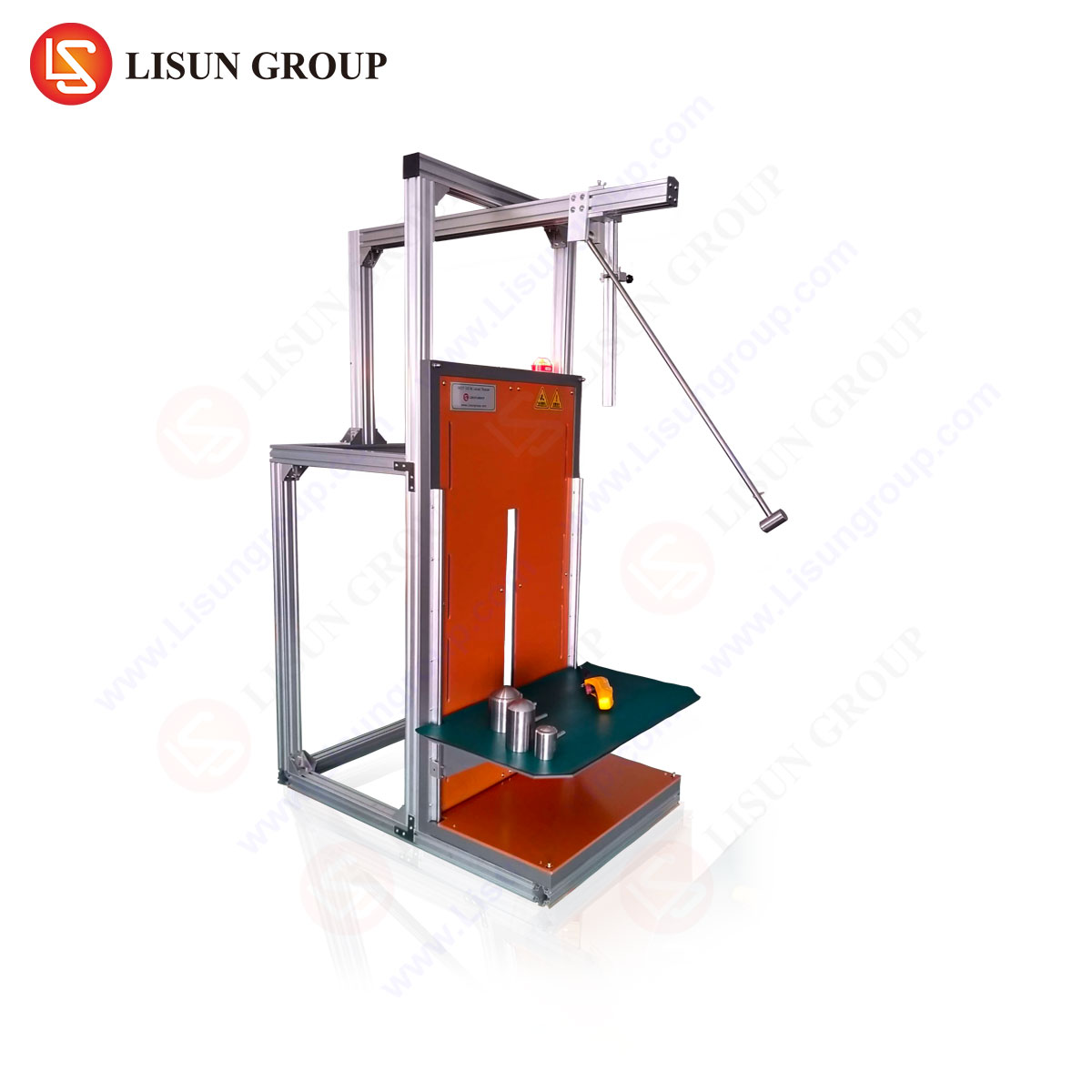
The RSY-LT Probador de encendido por hilo caliente: A Specialized Instrument for Compliance Verification
For components where fault conditions may involve overheating conductors, a related but distinct hazard is the ignition of surrounding materials by glowing or arcing wires. The LISÚN Probador de encendido por hilo caliente RSY-LT is engineered explicitly to evaluate this risk in accordance with standards such as IEC 60695-2-20 (Glow-wire flammability test on materials) and IEC 60950-1 (Information technology equipment safety). While not a direct AIV tester for air gaps, it addresses the arc ignition consequence scenario where thermal energy from an overloaded or faulty component could ignite adjacent insulating parts.
The tester operates on a defined principle: a pre-calibrated Kanthal wire (the “glow-wire”) is heated by an electrical current to a specific temperature, ranging from 550°C to 960°C, as required by the standard. This heated element is then applied with a defined force (1.0 N ± 0.2 N) to the test specimen for a set period (30 seconds typically). The apparatus meticulously monitors whether the specimen ignites, the duration of any flames, and whether dripping particles ignite a tissue paper substrate below. The primary measured outcome is the Glow-Wire Ignition Temperature (GWIT) or Glow-Wire Flammability Index (GWFI).
Technical Specifications and Operational Advantages of the RSY-LT
The RSY-LT system embodies precision and repeatability. Its specifications include a temperature control range up to 999°C with a resolution of 1°C and an accuracy of ± 10°C at 750°C. The timing functions are accurate to ± 0.1 seconds, critical for compliance with strict observational windows in standards. The unit features a digital PID temperature controller for stable heating, a mechanized test arm for consistent application force and alignment, and a built-in fume extraction port.
Its competitive advantages are multifaceted. First, its construction ensures exceptional repeatability, minimizing inter-operator and inter-lab variation—a critical factor in certification testing. Second, the integrated design enhances operator safety, containing potential flames and fumes. Third, its programmability allows for automated test sequences, storing multiple temperature and time profiles for different materials or components, thereby improving laboratory efficiency. This is particularly valuable for manufacturers in the Material eléctrico y electrónico y Office Equipment sectors, who must batch-test various plastic housings, PCB substrates, and insulation sleeving.
Application in Material and Component Qualification
The RSY-LT finds its primary use in the qualification stages of product development. For instance, a designer of a Household Appliance power supply must select a thermoplastic for the enclosure. Using the RSY-LT, they can determine the material’s GWFI, ensuring that an internal fault causing a component to overheat and contact the casing will not cause the casing itself to ignite. In Electrónica del automóvil, wiring harness clamps or connector bodies are tested to ensure they do not propagate fire from a short-circuit event.
Similarly, for Iluminación, the plastic components surrounding lamp holders and ballasts are subject to glow-wire testing. In Componentes eléctricos like switches and sockets, the insulating material must resist ignition from overheating terminals. The RSY-LT provides the empirical data needed to make compliant material choices, support technical construction file (TCF) submissions for the CE marking, and meet the requirements of UL, CSA, and other national standards.
Integrating AIV and Thermal Ignition Risk Assessments
A holistic safety engineering approach considers both the electrical initiation of an arc and its potential thermal consequences. A component may have a satisfactorily high Arc Ignition Voltage under clean, laboratory conditions. However, in the field, contamination or mechanical wear could lower this threshold. Once an arc is established, its plasma can exceed several thousand degrees Celsius, acting as a potent ignition source for adjacent materials. Therefore, the validation process for critical systems in Aerospace o Productos sanitarios often involves a two-tiered analysis: first, characterizing the AIV of contacts and clearances under various pollution degrees; second, validating that all materials within the potential arc zone have been tested with apparatus like the RSY-LT to have adequate resistance to ignition from such an extreme thermal event. This layered verification strategy is fundamental to achieving robust fault tolerance and mitigating fire risk.
Conclusión
Arc Ignition Voltage represents a fundamental electrical parameter with direct implications for product safety, reliability, and longevity across the technological spectrum. Its dependence on a multitude of physical and environmental variables necessitates rigorous, standardized testing integrated into the design validation cycle. While AIV testing focuses on the electrical conditions for discharge inception, complementary evaluations, such as those performed by the LISUN RSY-LT Hot Wire Ignition Tester, assess the subsequent fire hazard. Together, these methodologies provide engineers and certifiers with the critical data required to design products that not only function efficiently but also fail safely, thereby protecting both property and end-users. The ongoing evolution of materials and miniaturization in electronics will continue to make the precise understanding and control of these phenomena a cornerstone of electrical safety engineering.
Sección FAQ
Q1: How does the Glow-Wire test performed by the RSY-LT differ from a direct Arc Ignition Voltage test?
A1: The tests address different, though sometimes sequential, failure modes. An AIV test determines the voltage needed to electrically strike an arc across a gap. The Glow-Wire test simulates the thermal effects of an already-established fault (like an overheated connection or component) by applying a physically hot element to a material to see if it ignites. One assesses electrical breakdown; the other assesses flammability under thermal stress.
Q2: For which specific components in automotive electronics would glow-wire testing be mandated?
A2: Glow-wire testing is typically mandated for insulating parts and parts made of polymeric materials that are in close proximity to current-carrying parts which could overload. This includes connector housings, wire harness clips and guides, relay bodies, sensor housings, and PCB mounts that are within a specified distance (e.g., 13mm as per some standards) of potential heat sources.
Q3: Can the RSY-LT tester be used to certify products for both IEC and UL standards?
A3: Yes, the core methodologies in standards like IEC 60695-2-20 are harmonized with similar UL requirements (e.g., UL 746A). The RSY-LT is designed to perform tests in strict accordance with these international protocols. However, the specific test temperatures, durations, and pass/fail criteria must be selected based on the end-product standard (e.g., IEC 60950-1 for IT equipment or UL 60730 for automatic controls), which the laboratory engineer must configure.
Q4: What is the criticality of the applied force (1.0 N) during the test?
A4: The applied force is a controlled variable that significantly impacts heat transfer from the glow-wire to the test specimen. A higher force improves contact and thermal conduction, potentially leading to ignition at a lower wire temperature. The standardized force ensures that results are reproducible and comparable across different laboratories and material suppliers, eliminating a major source of test result variation.
Q5: In material selection, what is the practical difference between the GWFI and the GWIT?
A5: The Glow-Wire Flammability Index (GWFI) is the highest temperature at which a material does not ignite or, if it does, flames extinguish within 30 seconds after removal of the glow-wire and no dripping particles ignite the tissue. The Glow-Wire Ignition Temperature (GWIT) is a temperature 25°C (or 50°C in some cases) higher than the maximum temperature at which the material does not ignite for a period of 5 seconds. GWFI is often used for material pre-selection, while GWIT may be specified for thinner materials or specific component requirements.