


Arc Resistance Evaluation: Methodologies, Standards, and Advanced Testing Instrumentation
Introduction to Arc Resistance and Material Failure Mechanisms
Arc resistance represents a critical performance parameter for insulating materials and the components fabricated from them. It is formally defined as the ability of a material to resist the formation of a conductive path along its surface when subjected to a high-voltage, low-current arc. This failure mode is distinct from bulk dielectric breakdown, as it involves the progressive carbonization and tracking of the surface due to thermal degradation from the arc’s energy. The ensuing conductive track can lead to short circuits, ground faults, fire ignition, and catastrophic equipment failure. Evaluating arc resistance is therefore paramount across industries where electrical components operate in environments prone to arc initiation from dust, moisture, contamination, or switching events. The consequences of inadequate arc resistance range from diminished product lifespan in consumer electronics to life-threatening system failures in aerospace and medical applications.
The Physics of Surface Tracking and Progressive Carbonization
The underlying physical phenomenon during an arc resistance test is the localized thermal decomposition of the organic polymer matrix. When an electrical arc is established across the surface of an insulating material, the intense heat—often exceeding several thousand degrees Kelvin—pyrolyzes the polymer. This pyrolysis liberates carbonaceous byproducts. With repeated or sustained arcing, these carbon deposits accumulate, forming a semi-conductive or fully conductive path on what was initially an insulating surface. The propensity for tracking is influenced by a complex interplay of material properties: polymer chemistry, filler type and concentration, surface energy, thermal conductivity, and hydrophobicity. For instance, materials with high inorganic filler content, such as alumina-trihydrate in certain thermosets, can exhibit enhanced arc resistance as the fillers absorb heat and release water vapor, disrupting carbon chain formation. The process is not instantaneous but progressive, making the standardized measurement of the time-to-failure a key metric for material comparison and qualification.
International Standards Governing Arc Resistance Testing
To ensure consistency and reproducibility, arc resistance testing is prescribed by several international standards, each tailored to specific voltage regimes, applications, and failure criteria. The most prevalent standards include:
- IEC 61621: This standard, titled “Dry, solid insulating materials – Resistance test to high-voltage, low-current arc discharges,” is a foundational method. It employs a fixed, progressive arc current schedule and defines failure as the formation of a conductive path that reduces the surface insulation resistance below a specified threshold or causes sustained arcing.
- ASTM D495: The “Standard Test Method for High-Voltage, Low-Current, Dry Arc Resistance of Solid Electrical Insulation” is a widely recognized ASTM standard. It utilizes a similar but distinct progressive current sequence to IEC 61621 and is extensively referenced in North American industries.
- UL 746A: Underwriters Laboratories’ standard for “Polymeric Materials – Short Term Property Evaluations” incorporates arc resistance testing as a critical safety metric for materials used in electrical equipment. Compliance is often a de facto requirement for market access in the United States and Canada.
These standards specify stringent requirements for electrode geometry (typically tungsten rods of defined sharpness), arc initiation circuitry, environmental conditions, and failure detection logic. Adherence to these protocols is non-negotiable for laboratories providing certification data to OEMs and regulatory bodies.
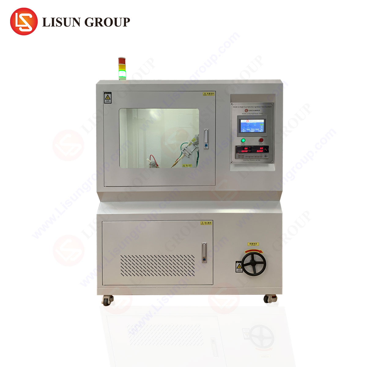
The HCAI-2 Prueba de ignición por arco de alta corriente System: Architecture and Operating Principles
El LISÚN HCAI-2 High Current Arc Ignition Test System represents a sophisticated instrumentation platform engineered for precise, repeatable, and standards-compliant arc resistance evaluation. Its design addresses the exacting demands of modern material labs serving the automotive, aerospace, and high-reliability electronics sectors. The system’s core function is to generate, control, and monitor high-current arc discharges according to predefined test regimens, while accurately detecting the point of material failure.
The system’s architecture is built around a high-stability, programmable power supply capable of delivering the requisite voltage (typically up to 12.5kV) and current sequences. A central microcontroller governs the test schedule, precisely timing the duration of each arc stage and managing the current ramp profile as per the selected standard (e.g., the 10-step sequence of ASTM D495). The electrode assembly is mounted within a transparent, interlocked test chamber to contain debris and protect the operator. A critical subsystem is the failure detection circuit, which continuously monitors the resistance across the test specimen. The system is designed to terminate the test instantaneously upon detecting the predefined failure condition—often a drop in resistance or a sustained arc—and records the elapsed time to the nearest 0.1 second. This time-to-track value is the primary quantitative output of the test.
Technical Specifications and Calibration Integrity of the HCAI-2 System
The efficacy of any test instrument is contingent upon the accuracy and stability of its specifications. The HCAI-2 system is characterized by parameters that ensure laboratory-grade results:
- Arc Current Range: 10 mA to 100 mA, programmable in precise steps.
- Open Circuit Voltage: 0 to 12.5 kV, ensuring sufficient potential to initiate and maintain arcs across a wide variety of material surface resistivities.
- Timing Accuracy: Better than ±0.1% for stage durations, crucial for the progressive test sequences where each stage may last only 60 seconds.
- Failure Detection Sensitivity: Configurable threshold for resistance drop, typically in the range of 1 MΩ to 100 kΩ, with a response time of less than 10 milliseconds.
- Electrode Configuration: Tungsten carbide electrodes, conforming to standard-specified geometries and angles, mounted on a precision positioning stage with adjustable gap distance (commonly 6.0 mm ± 0.1 mm).
- Calibration: The system incorporates routines for the periodic calibration of high voltage, current measurement, and timing circuits. Traceability to national metrology institutes is maintained through certified reference instruments.
This combination of high precision, robust construction, and adherence to standardized geometries ensures that data generated by the HCAI-2 is directly comparable across different testing laboratories and material batches, a necessity for global supply chains.
Application Across Critical Industrial Sectors
Arc resistance data generated by systems like the HCAI-2 informs material selection and component design in a diverse array of industries:
- Electrónica del automóvil: Under-hood components, battery management systems (BMS) for electric vehicles, and charging connectors are exposed to vibration, thermal cycling, and potential contamination. Arc-resistant materials prevent tracking in connectors, sensor housings, and power electronic modules.
- Aerospace and Aviation Components: The low-pressure, high-altitude environment can lower the breakdown voltage, making arc resistance vital for wire insulation, connector backshells, and cockpit switchgear in both commercial and military aircraft.
- Productos sanitarios: For life-support and diagnostic equipment, reliability is paramount. Materials used in switches, internal insulation of imaging systems (CT, MRI), and portable defibrillator housings must demonstrate high arc resistance to prevent internal faults.
- Industrial Control Systems: Motor controllers, programmable logic controller (PLC) terminals, and industrial switchgear operate in environments with conductive dust, oil mists, and humidity. Arc-resistant barrier strips and insulator plates are essential for functional safety.
- Iluminación: High-intensity discharge (HID) lamp ballasts and LED driver circuits generate significant heat and voltage. Sockets and internal insulators must resist tracking from possible carbon deposits or moisture ingress.
- Electrical Components: The most direct application is in switches, circuit breakers, sockets, and terminal blocks, where arcing occurs during normal make/break operations or under fault conditions.
- Telecommunications Equipment: Power supply units and surge protection devices for base stations and data centers utilize arc-resistant plastics to mitigate risks from power cross faults or lightning-induced surges.
- Cable and Wiring Systems: Specialty cables for mining, shipbuilding, and industrial machinery often have arc-resistant outer jackets or insulation compounds as a key safety feature.
Comparative Advantages in a Laboratory Setting
The HCAI-2 system provides distinct operational advantages that translate to higher data integrity and laboratory efficiency. Its fully automated test sequencing eliminates operator timing errors inherent in manual or semi-automated setups. The digital failure detection, with its millisecond response, provides an unambiguous and repeatable endpoint, removing subjective visual interpretation of “when a track forms.” The integrated data logging system automatically records test parameters, time-to-failure, and environmental conditions for each specimen, streamlining report generation and audit trails. Furthermore, the system’s robust arc suppression and chamber interlock design enhance operator safety when dealing with high-voltage arcs and potential outgassing from test specimens. When compared to legacy test sets, these features reduce test variability, increase throughput, and ensure unwavering compliance with the procedural minutiae of IEC, ASTM, and UL standards.
Interpreting Test Data and Correlating to Real-World Performance
The primary datum, the arc resistance time in seconds, is a comparative index, not an absolute predictor of service life. A material scoring 180 seconds on the ASTM D495 test is categorically more resistant than one failing at 120 seconds. However, engineers must correlate this data with other material properties and the specific application environment. For example, a material with excellent arc resistance but poor hydrolytic stability would be unsuitable for a humid environment. Similarly, UV resistance and comparative tracking index (CTI) data are often reviewed in tandem. Advanced laboratories use arc resistance testing as part of a failure analysis (FA) workflow. By subjecting field-failed components and virgin materials to the same controlled arc test, engineers can determine if material degradation or a substandard formulation was a contributing factor in the field failure, guiding corrective actions in design or manufacturing.
Future Trends and Evolving Material Challenges
The ongoing electrification of transport, the miniaturization of electronics, and the adoption of wide-bandgap semiconductors (SiC, GaN) are driving new material challenges. Higher operating temperatures and switching frequencies in power electronics demand insulating materials with simultaneously superior arc resistance, thermal conductivity, and high-temperature stability. The development of novel nanocomposites and ceramic-polymer hybrids is a direct response to these needs. Consequently, test instrumentation must evolve in parallel. Future iterations of systems like the HCAI-2 may incorporate in-situ thermal imaging to map heat dissipation during arcing, or spectroscopic analysis of plasma composition during testing. The fundamental standard test methods remain, but the supporting diagnostic capabilities of the test equipment will expand to provide deeper insights into material behavior under electrical stress.
Sección FAQ
Q1: What is the key difference between the High Current Arc Ignition test and a Comparative Tracking Index (CTI) test?
Both evaluate surface degradation, but under different stress conditions. The Arc Resistance test (e.g., with the HCAI-2) uses a high-voltage, low-current arc discharged in air across the surface, simulating faults like broken conductors. The CTI test uses a lower voltage with a conductive electrolyte solution (e.g., ammonium chloride) dripping onto the surface, simulating contamination. They assess different failure modes and are complementary material properties.
Q2: Can the HCAI-2 system be configured to test according to multiple standards?
Yes. A primary design feature of the HCAI-2 is its programmable test scheduler. The controller can be set to execute the specific current progression stages, stage durations, and failure criteria defined in IEC 61621, ASTM D495, or other user-defined sequences. This allows a single instrument to serve multiple testing protocols required by different customers or regulatory regions.
Q3: How critical is electrode maintenance and replacement in arc resistance testing?
Extremely critical. Standards mandate specific electrode tip geometry and sharpness. Tungsten electrodes erode during testing, changing the gap and tip radius, which directly affects arc characteristics and reproducibility. The HCAI-2’s precision electrode holders facilitate consistent re-positioning, but operators must follow a strict schedule of inspection, re-sharpening, or replacement as per the standard’s guidelines to ensure valid results.
Q4: For a material that does not form a conductive track, how does the test end?
The standardized tests (IEC 61621, ASTM D495) have a maximum duration, typically 420 seconds or until a specified final current stage is completed. If the material withstands the full progressive sequence without meeting the failure criteria (i.e., no low-resistance track forms), it is reported as having an arc resistance time greater than the final stage’s elapsed time (e.g., “> 420 s”). This indicates superior performance.
Q5: What specimen preparation is typically required before testing?
Specimens are usually flat plaques of a defined minimum thickness (e.g., 3 mm). The surface must be clean and free of contaminants like mold release agents, which can drastically alter results. Some standards may specify a light abrasive cleaning prior to test. Conditioning in a controlled temperature and humidity environment for 24-48 hours prior to testing is also commonly required to establish a known baseline state.