


The Role of Controlled Impact Testing in Validating Product Structural Integrity
In the globalized marketplace, product reliability transcends mere feature functionality; it is a fundamental covenant of safety, durability, and brand trust. For manufacturers across a spectrum of industries—from consumer electronics to critical aerospace components—the ability to withstand mechanical shocks incurred during handling, transportation, and end-use is non-negotiable. Drop testing, a subset of environmental stress screening, serves as the empirical cornerstone for validating this resilience. By subjecting products and their packaging to controlled, reproducible impacts, drop testers provide quantifiable data on structural robustness, design flaws, and protective material efficacy. This article delineates the methodologies, standards, and technological implementations of drop testing, with a specific examination of integrated systems such as the LISÚN DT-60KG Drop Tester, to elucidate how this discipline ensures product reliability from design validation to quality assurance.
Fundamental Principles of Simulated Impact Dynamics
At its core, drop testing is an application of classical mechanics, specifically the conservation of energy and impulse-momentum theory. When a test specimen is released from a predetermined height, its potential energy converts to kinetic energy immediately prior to impact. The subsequent collision with a rigid strike surface generates a high-magnitude, short-duration shock pulse. The primary objective of the test is not merely to observe if the unit fails, but to measure its response to this transient event. Key parameters under analysis include the peak acceleration (measured in g-forces), velocity change, pulse duration, and the shock response spectrum. The shape of the deceleration pulse—half-sine, trapezoidal, or sawtooth—is dictated by the interaction between the specimen’s stiffness and the impedance of the strike surface.
Modern drop testers meticulously control these variables to simulate real-world conditions. Standardized test protocols, such as those outlined in IEC 60068-2-31, MIL-STD-810G Method 516.8, and ISTA series procedures, define specific drop angles, orientations (face, edge, corner), and surface materials. For instance, testing a telecommunications router may require corner drops onto plywood over concrete to simulate a fall from a shelf onto a subfloor, while an automotive electronic control unit (ECU) might be subjected to repeated face drops from a lower height to mimic vibration-induced loosening and impact within a vehicle door panel.
Methodological Framework for Standardized Drop Testing
A rigorous drop testing regimen follows a phased methodology, integral to the product development lifecycle. The initial phase involves Definition of Test Profiles, where real-world transit and use environments are analyzed. Data loggers may be employed in shipping trials to record actual g-forces experienced by packages. This field data informs laboratory test severities, ensuring simulations possess ecological validity.
El Fixture and Specimen Preparation phase is critical. The unit under test (UUT) must be secured in a manner that does not artificially dampen the impact or alter its natural frequency. For products like household appliances or industrial control systems, internal mass simulators may be used if operational units are unavailable. The UUT is often instrumented with tri-axial accelerometers, with data acquisition systems capturing the shock waveform at sampling rates exceeding 10 kHz to avoid aliasing.
Execution and Monitoring involves performing the drops in the sequence mandated by the relevant standard. A typical sequence for an electrical component like a molded-case circuit breaker might include two drops per axis on each of the six faces. After each impact, the unit may undergo interim functional checks—continuity tests for switches, dielectric strength tests for sockets, or operational boot-ups for medical devices—to identify cumulative damage.
Finally, Post-Test Analysis and Failure Mode Evaluation transforms raw data into actionable intelligence. Engineers examine not only whether the product powered on, but also for latent defects: cracked solder joints in automotive electronics, lens dislocation in lighting fixtures, or memory corruption in office equipment. The failure mode, coupled with the recorded shock pulse, guides design iterations in material selection, internal bracing, or PCB mounting.
Instrumentation and Control in Modern Drop Testing Apparatus
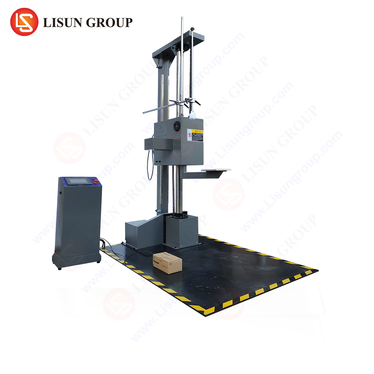
The fidelity of drop testing is wholly dependent on the precision and capabilities of the apparatus. A sophisticated drop tester integrates mechanical design with advanced measurement and control systems. The LISUN DT-60KG Drop Tester exemplifies this integration, designed to deliver repeatable, standards-compliant impacts for products up to 60 kg—a capacity relevant for larger assemblies like uninterruptible power supplies, aerospace avionics cases, or bundled cable and wiring systems.
The system operates on an electromagnetic release and braking principle. A digitally controlled electromagnetic holder secures the test platform at a user-defined height, programmable via a human-machine interface (HMI) with an accuracy typically within ±10 mm. Upon command, the holder disengages cleanly, allowing the platform and specimen to fall freely without inducing lateral motion or rotation that would invalidate the impact angle. A pneumatic or mechanical braking system arrests the platform post-impact to prevent secondary, uncontrolled bouncing.
Key specifications of such a system underscore its technical rigor:
- Test Weight Capacity: 60 kg, accommodating a broad range of industrial products.
- Drop Height Range: 300–1500 mm (or similar), covering most commercial and military test requirements.
- Impact Surface: A rigid, flat, monolithic steel plate, often accompanied by interchangeable surfaces (e.g., laminated wood per ISTA) mounted on a massive base to approximate an infinite impedance.
- Sistema de control: Microprocessor-based, allowing for pre-programming of drop sequences, heights, and counts. It ensures the strike surface is consistently perpendicular to the direction of fall.
- Características de seguridad: Interlocked guards, emergency stop circuits, and fail-safe braking protect both the operator and the instrumentation.
The competitive advantage of such a system lies in its repeatability and data integrity. Manual drop methods are prone to variability in release angle, surface alignment, and measurement error. An automated tester like the DT-60KG eliminates these variables, ensuring that any performance delta between test cycles is attributable to the product or packaging itself, not the test apparatus. This is paramount for comparative testing of different cushioning materials for consumer electronics or for validating manufacturing consistency in medical device enclosures.
Aplicaciones específicas de la industria e imperativos de cumplimiento
The application of drop testing is tailored to the unique failure modes and regulatory landscapes of each sector.
- Electrical & Electronic Equipment / Consumer Electronics: For smartphones, tablets, and laptops, tests focus on corner and edge drops onto hard surfaces from typical handset heights (e.g., 1.2m). The integrity of glass displays, housing seams, and internal board retainers is assessed. The DT-60KG’s capacity can be leveraged for larger items like all-in-one desktop computers or studio monitors.
- Electrónica del automóvil: ECUs, sensors, and infotainment systems are tested for “bench handling” drops (e.g., 1m onto concrete) as well as shock within mounted assemblies. Robustness against impacts that could occur during vehicle assembly or aftermarket installation is critical.
- Lighting Fixtures & Electrical Components: LED luminaires, switches, and sockets are evaluated for impacts that may occur during installation or service. A ceramic light socket, for instance, must not crack in a way that exposes live parts. Testing validates compliance with safety standards like UL 1598 or IEC 60669-1.
- Productos sanitarios: Reliability can be a matter of life safety. Portable diagnostic devices, insulin pumps, and surgical tool handles undergo drop testing to ensure no single impact creates sharp edges, compromises sterility barriers, or causes functional degradation that could lead to misdiagnosis or treatment error, per IEC 60601-1 general safety standards.
- Aerospace & Aviation Components: While in-flight shocks are rare, ground handling and cargo loading impose significant risks. Test protocols are exceptionally severe, often involving multiple orientations onto steel plates from heights specified in DO-160G, Section 8.
- Telecommunications / Industrial Control Systems: Ruggedized routers, PLCs, and field instruments are tested for durability in industrial environments. The focus is on maintaining electrical continuity and sealing integrity (IP rating) after repeated shocks.
Quantitative Analysis and the Interpretation of Shock Data
The output of an instrumented prueba de caída is a time-history acceleration curve. Analysis extends beyond peak g. Engineers calculate the Velocity Change (ΔV) by integrating the acceleration curve; a significant deviation from the theoretical ΔV (√2gh) indicates energy loss due to plastic deformation of the specimen or packaging. The Shock Response Spectrum (SRS) is a more advanced tool, predicting how the shock pulse would excite the natural frequencies of secondary structures within the product, such as a relay on a PCB or a lens within a fixture.
Consider the following comparative data for a hypothetical plastic enclosure for an industrial sensor:
| Test Condition | Peak Acceleration (g) | Pulse Duration (ms) | ΔV (m/s) | Functional Result |
|---|---|---|---|---|
| Face Drop, 1m, No Packaging | 850 | 3 | 4.12 | PCB Mount Crack, Sensor Offset |
| Face Drop, 1m, 2″ Foam | 220 | 8 | 4.05 | No Damage, Operational |
| Corner Drop, 0.75m, No Packaging | 1250 | 1.5 | 3.61 | Case Fracture, Electrical Short |
This data reveals that the unprotected product is vulnerable, particularly to corner impacts which generate higher g-forces. The foam packaging successfully attenuates the shock by extending the pulse duration, reducing the acceleration transmitted to the product. The corner drop, even from a lower height, induces a more damaging, higher-frequency pulse, highlighting a critical design weakness in the enclosure’s reinforcement at corners.
Integration into a Comprehensive Reliability Engineering Program
Drop testing is most effective when not conducted in isolation. It forms a critical link in a chain of validation that includes vibration testing (to simulate transit), climate cycling (for material expansion/contraction), and combined environment testing. A product may survive a singular drop but fail when the drop follows extended vibration that has loosened fasteners. Furthermore, drop test results feed directly into Failure Mode, Effects, and Criticality Analysis (FMECA), informing risk assessments and guiding design-for-reliability (DfR) initiatives.
The implementation of a system like the LISUN DT-60KG within a quality laboratory standardizes this critical stress screening. Its programmability allows for the creation of bespoke test profiles that mirror complex supply chain journeys—a pathway that may include manual handling in a warehouse, parcel sorting automation drops, and final delivery. By providing unambiguous, repeatable evidence of structural adequacy or deficiency, such apparatuses empower engineers to make data-driven decisions, ultimately reducing warranty claims, enhancing user safety, and fortifying brand reputation in competitive global markets.
Preguntas más frecuentes (FAQ)
Q1: How does the electromagnetic release mechanism in a tester like the DT-60KG improve test accuracy compared to manual or mechanical release?
A1: Manual releases can impart lateral forces or rotation, altering the intended impact angle and orientation. Mechanical releases may exhibit friction or bounce. An electromagnetic system provides a instantaneous, clean disengagement purely under the force of gravity, ensuring the drop is perfectly vertical and the impact face is parallel to the strike plate. This eliminates apparatus-induced variability, making results purely reflective of the specimen’s performance.
Q2: For a medical device manufacturer, what considerations beyond basic drop height are needed when creating a test plan?
A2: The test plan must be risk-based. Considerations include: the device’s mass and most fragile orientation; the worst-case clinical environment (e.g., ICU vs. home use); testing of both the device itself and its transit packaging; interim functional checks after each drop; and post-test inspection for subtle defects like cracked seals or battery door latch degradation that could compromise safety or performance. Compliance with specific clauses in IEC 60601-1-11 (for home healthcare) is also mandatory.
Q3: Can the DT-60KG be used to test the performance of packaging alone, without a product inside?
A3: While possible, it is not standard practice. Packaging testing (per ISTA Series 1, 2, etc.) is always conducted with a representative product or a calibrated dummy load of identical weight, center of gravity, and fragility. The interaction between the product’s stiffness and the packaging’s cushioning properties is what determines the transmitted shock. Testing empty packaging yields irrelevant data.
Q4: How often should the calibration and verification of a drop tester be performed?
A4: Critical parameters like drop height accuracy, release mechanism function, and strike plate levelness should be verified prior to each test series. A full metrological calibration of the height scale and associated control systems should be performed annually or per the manufacturer’s recommendation, traceable to national standards. Regular maintenance of the braking system and structural inspection for wear are also essential to ensure ongoing accuracy.