


Generating IK Impact Test Standards: A Comprehensive Guide for Product Durability Testing
Introduction to Mechanical Impact Protection and the IK Code
In the rigorous landscape of product design and validation, ensuring resilience against mechanical impacts is a non-negotiable criterion across a multitude of industries. The International Electrotechnical Commission (IEC) standard 62262, harmonized in Europe as EN 62262, provides the definitive framework for quantifying this resilience: the IK code. The “IK” designation, derived from the German “Impakt-Klasse” (Impact Class), offers a standardized scale from IK00 to IK10 that specifies the degree of protection an enclosure provides against external mechanical impacts. Unlike subjective assessments of “ruggedness,” the IK code delivers a reproducible, quantifiable metric essential for compliance, specification, and risk mitigation. This guide delineates the principles, methodologies, and applications of IK impact testing, serving as a critical resource for engineers, quality assurance professionals, and product specifiers committed to substantiating product durability through empirical evidence.
Deconstructing the IK Rating Scale: Energy, Tools, and Impacts
The IK rating scale is fundamentally an energy scale, where each code corresponds to a specific impact energy measured in joules (J). The progression is logarithmic, with IK00 indicating no protection and IK10 representing the highest defined level of resistance. Crucially, the standard stipulates not only the energy but also the striking element (hammer) to be used and the number and distribution of impacts. For ratings IK01 through IK06, a pendulum hammer is typically employed, with the energy calibrated via the hammer’s mass and drop height. Ratings IK07 through IK10 mandate the use of a spring-operated hammer, which delivers a consistent, high-velocity impact.
A critical nuance often overlooked is that the IK rating defines the protection level of the enclosure itself, not the internal components. A device may survive an IK10 impact to its housing, but internal circuit boards could still be damaged by shock transmission. Therefore, IK testing is frequently complemented by shock and vibration testing (e.g., IEC 60068-2-27) for a complete mechanical robustness profile. The following table outlines the core parameters for key IK ratings:
| IK Code | Impact Energy (Joules) | Typical Testing Tool |
|---|---|---|
| IK04 | 0.5 J | Pendulum Hammer |
| IK06 | 1 J | Pendulum Hammer |
| IK07 | 2 J | Spring Hammer (0.5 kg mass) |
| IK08 | 5 J | Spring Hammer (1.7 kg mass) |
| IK09 | 10 J | Spring Hammer (5 kg mass) |
| IK10 | 20 J | Spring Hammer (5 kg mass) |
The Physics of Controlled Impact: Spring Hammer Methodology
For high-energy testing (IK07-IK10), the spring hammer apparatus is the mandated instrument. Its operation is governed by precise physics: a mass is propelled linearly by the release of a calibrated spring, striking the test sample at a defined velocity. The kinetic energy imparted is calculated as E = ½mv², where m is the mass of the striking element and v is its instantaneous velocity at the moment of impact. The standard rigorously defines the hammer’s geometry, material (polyamide), radius of striking face, and the spring’s force characteristics to eliminate variability. This ensures that an IK08 rating achieved in a laboratory in Germany is functionally equivalent to one certified in Japan, enabling global market access.
The test procedure requires impacts on the enclosure’s most vulnerable points—typically corners, edges, and areas above internal supports—as identified during a pre-test assessment. The sample must withstand a prescribed number of impacts (usually five per selected point) without incurring damage that violates its specified degree of protection. Post-test evaluation examines for cracks, permanent deformation exceeding allowable limits, or any opening that would allow a standardized test probe to access hazardous live parts or moving components.
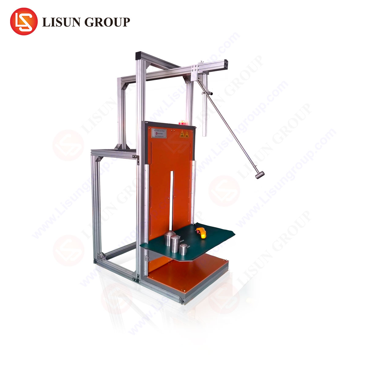
Instrumentation Spotlight: The LISÚN IK07-10VT IK Test System
Implementing IK07-IK10 testing demands instrumentation of exceptional accuracy, repeatability, and durability. The LISUN IK07-10VT IK Test apparatus exemplifies the engineering required for such standards-compliant validation. This vertical test system is engineered specifically for the rigorous demands of high-energy impact testing per IEC 62262, IEC 60068-2-75, and related standards.
The system’s core mechanism is a vertically mounted, pneumatically assisted launch system that propels the standardized hammer masses (0.5 kg, 1.7 kg, 5 kg) along a low-friction guide column. This vertical design ensures perfect alignment and eliminates the parasitic lateral forces that can occur in less refined setups. A key feature is its integrated velocity measurement system, which verifies the impact energy for every single test strike. By directly measuring the hammer’s speed immediately prior to impact, the system provides empirical confirmation that the required energy (e.g., 5.0 J ±0.5 J for IK08) has been delivered, moving beyond theoretical calibration to data-driven verification.
Specifications of the LISUN IK07-10VT include an adjustable impact height range to accommodate various sample sizes, a sturdy test baseplate with fixture provisions, and a safety enclosure with interlock. Its programmable logic controller (PLC) allows for automated test sequences, including strike count and hammer selection, minimizing operator influence and enhancing reproducibility. For industries where audit trails are critical, such as medical devices or automotive electronics, this programmability and data logging are indispensable.
Aplicaciones específicas de la industria e imperativos de cumplimiento
The application of IK testing is pervasive, dictated by both functional requirements and regulatory frameworks.
- Electrical and Electronic Equipment, Industrial Control Systems: Enclosures for programmable logic controllers (PLCs), motor drives, and remote terminal units (RTUs) in factory environments are subject to tool drops, accidental kicks, and debris impacts. An IK08 or IK09 rating is often specified to ensure operational continuity in harsh industrial settings.
- Iluminación: Public area lighting, industrial high-bay lights, and emergency exit signs require protection from vandalism and accidental contact. IK ratings (commonly IK08-IK10) are a core part of product datasheets and are frequently mandated in public procurement tenders.
- Electrónica del automóvil: Components mounted in vehicle doors, undercarriages, or engine bays, such as sensors, control modules, and junction boxes, must withstand stone chips, flying debris, and maintenance impacts. IK testing simulates these environmental hazards.
- Electrodomésticos y electrónica de consumo: While often lower energy (IK04-IK06), testing ensures products like robotic vacuum cleaners, smart thermostats, or outdoor security cameras can survive typical household mishaps.
- Medical Devices and Telecommunications Equipment: Equipment used in ambulances, field hospitals, or telecom cabinets must endure transport and handling shocks. An IK rating provides a benchmark for mechanical integrity, complementing ingress protection (IP) ratings against dust and water.
- Aerospace and Aviation Components: Though governed by stringent DO-160 or MIL-STD standards, IK principles apply to ground-handling equipment and external panel durability, where hangar debris or tool slippage poses a risk.
Designing for IK Compliance: A Proactive Engineering Approach
Achieving a target IK rating is not a matter of fortuitous material selection but a deliberate design process. Engineers must integrate mechanical analysis from the conceptual phase. Finite Element Analysis (FEA) can model stress concentrations from point impacts, guiding rib placement, wall thickness gradients, and material selection. Ductile engineering polymers like polycarbonate blends or reinforced nylons are common, but design features—such as internal reinforcing ribs, strategic coring to maintain stiffness-to-weight ratios, and the avoidance of sharp internal corners that act as stress risers—are equally critical.
The interface between the enclosure and its mounting or internal assemblies is another focal point. A well-designed housing can shatter if shock energy is transmitted undamped to brittle internal components. Decoupling through elastomeric grommets, strategic use of foam, and careful placement of printed circuit board (PCB) mounts are essential secondary strategies. The ultimate validation, however, remains physical testing on production-representative samples, as material inconsistencies, molding parameters, and assembly tolerances can all affect the final impact performance.
Interpreting Test Results and Failure Mode Analysis
A “pass” or “fail” determination is merely the starting point for analysis. A comprehensive test report should document the exact impact locations, the energy verified for each strike, and a detailed photographic record of any damage. Common failure modes include:
- Crazing/Cracking: Radial or concentric cracks emanating from the impact point, indicating brittle failure or insufficient material impact strength.
- Permanent Deformation: Excessive denting or yielding that compromises aesthetic requirements, dimensional tolerances for seals, or internal clearances.
- Fastener Failure: Shearing of screw bosses or detachment of snap-fit features, highlighting weak points in the assembly strategy.
- Functional Compromise: While the enclosure may remain intact, internal components may become dislodged or connections severed.
Root cause analysis of these failures feeds directly back into the design iteration cycle, enabling targeted improvements. For instance, cracking may be addressed by increasing wall thickness, adding radii, or switching to a more impact-resistant polymer grade.
The Synergy of IK and IP Ratings in Holistic Product Protection
It is imperative to contextualize IK ratings within the broader spectrum of environmental protection. The IP (Ingress Protection) code, detailed in IEC 60529, defines protection against solids and liquids. These two standards are symbiotic. An impact that cracks an enclosure (an IK failure) will almost certainly compromise its IP rating. Consequently, products destined for harsh environments—such as outdoor industrial switches (requiring IP67 and IK09) or marine navigation lights—must be validated for both standards, often sequentially. The order of testing is critical: IK impact testing should generally be performed after IP testing, as the impacts could create openings that would falsely cause an IP test to fail. The combined IK/IP designation provides a complete shorthand for mechanical and environmental robustness, a powerful specification tool for engineers and purchasers alike.
Conclusión
The IK impact test standard transcends a simple compliance checkbox; it is a fundamental engineering discipline that bridges design intent with real-world performance. By providing a codified, repeatable method for assessing mechanical impact resistance, it empowers manufacturers to build credibility, reduce field failure rates, and meet stringent industry-specific requirements. As products continue to proliferate in increasingly demanding environments—from smart city infrastructure to autonomous vehicle systems—the empirical evidence provided by rigorous IK testing, facilitated by precise instrumentation like the LISUN IK07-10VT system, will remain a cornerstone of durable and reliable product design.
Sección FAQ
Q1: Can a product have both an IK and an IP rating, and how are they related?
Yes, and they are frequently specified together. The IK rating defines mechanical impact resistance, while the IP rating defines protection against ingress of dust and water. They are complementary but independent. However, a failure in an IK test (e.g., a crack) will likely lead to a failure in the IP rating, as the integrity of the seal is compromised. Testing sequence is important; IK impact testing is typically conducted after IP testing.
Q2: Why is velocity measurement critical in an IK07-IK10 test system like the LISUN IK07-10VT?
The impact energy is a function of mass and the square of the velocity. Small variations in velocity result in significant variations in delivered energy. A system that relies solely on spring calibration and drop height may experience energy drift due to friction, wear, or atmospheric conditions. Direct velocity measurement before each impact provides objective, verifiable proof that the exact energy mandated by the standard (e.g., 20 J ±2 J for IK10) was achieved, ensuring test validity and repeatability.
Q3: Our product is made of metal. Is IK testing still relevant?
Absolutely. While metals generally have high impact resistance, design features like thin gauge sections, welded seams, coated surfaces, and the performance of mounted components (e.g., glass windows, plastic buttons) are still vulnerable. IK testing verifies that the assembled product, not just the base material, can withstand the specified impacts without functional or safety-related damage.
Q4: How do we select the appropriate IK rating for our new product?
Selection is based on a risk assessment of the intended use environment. Consider historical failure modes of similar products, industry norms (e.g., IK08 is common for industrial equipment), specific customer requirements, and any relevant regional or sector-specific regulations. Field environments with potential for tool drops or vandalism demand higher ratings (IK08-IK10), while controlled indoor settings may only require lower ratings (IK04-IK06).
Q5: After an IK test pass, is any additional mechanical testing required?
IK testing addresses localized, high-energy, low-frequency impacts. It is often part of a broader mechanical testing suite. Depending on the application, you may also need to consider:
- Shock Testing (IEC 60068-2-27): For high-acceleration, short-duration pulses experienced during transportation or operation.
- Vibration Testing (IEC 60068-2-64): For repetitive stress experienced during shipping or in operational environments like vehicles or machinery.
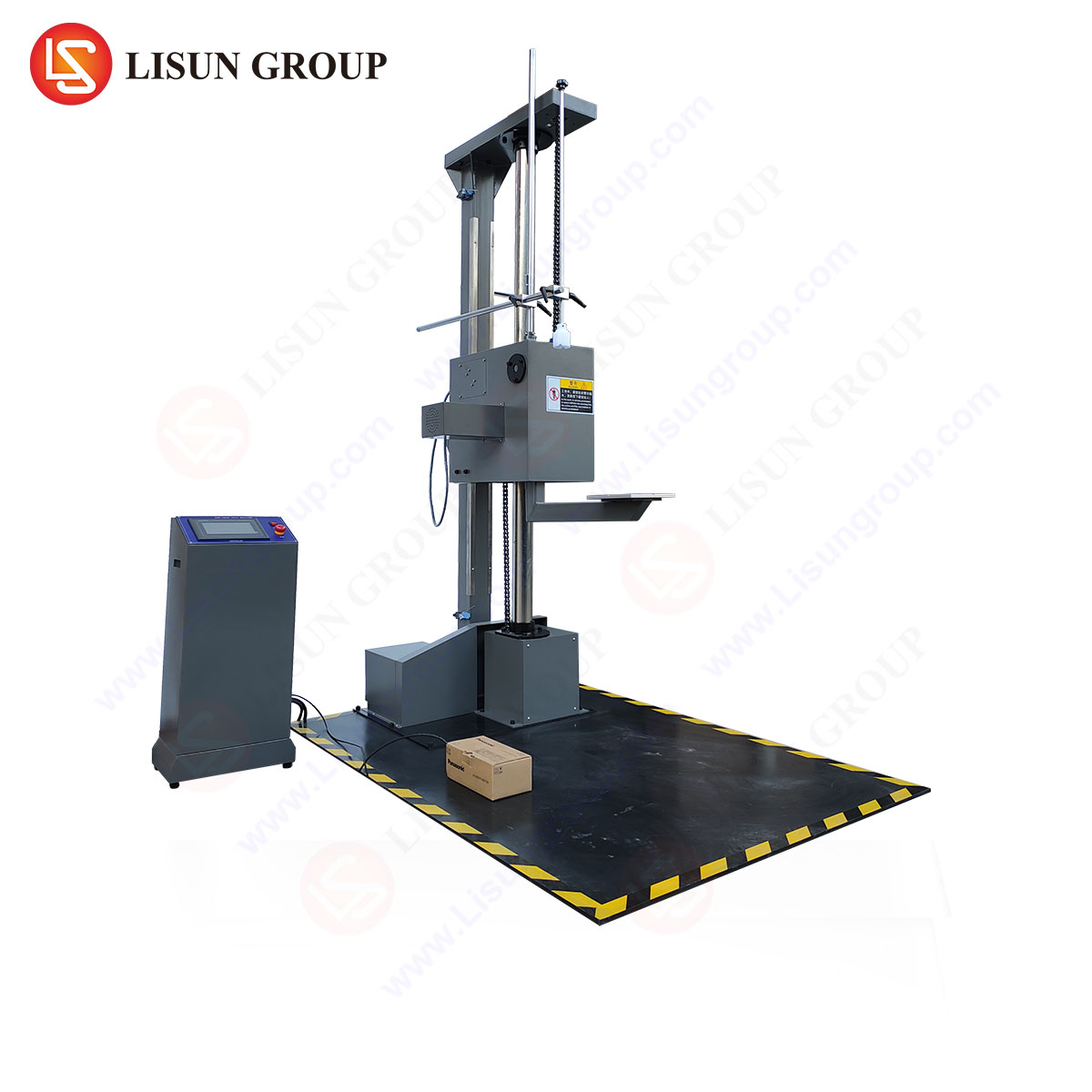
- Drop Testing (IEC 60068-2-31): For assessing resilience to free-fall accidents during handling.
A comprehensive durability profile integrates data from all relevant test types.