


Material Durability Analysis: Quantifying Arc Fault Resistance in Electrical Components
Introduction: The Imperative of Arc Resistance Testing
The long-term operational integrity of electrical and electronic components is fundamentally contingent upon the durability of their insulating materials and contact systems. Among the most severe stressors these materials face is exposure to electrical arcing, a plasma discharge resulting from the ionization of air or other media between conductive parts at differing potentials. Arc events can be precipitated by insulation degradation, contact wear, contamination, loose connections, or transient voltage surges. The consequences of insufficient arc resistance are severe, ranging from gradual carbon tracking that leads to leakage currents and eventual short circuits, to instantaneous, high-energy arcs capable of igniting surrounding materials, causing catastrophic equipment failure, and presenting significant fire and safety hazards.
A rigorous, quantifiable analysis of a material’s or component’s ability to withstand and extinguish electrical arcs is therefore not merely a quality check, but a critical safety and reliability engineering discipline. This analysis directly informs material selection, product design, failure mode analysis, and compliance with international safety standards. The following discourse provides a detailed examination of arc durability testing methodologies, with a specific focus on high-current arc ignition resistance as a pivotal performance metric across diverse industries.
Fundamental Mechanisms of Arc-Induced Material Degradation
The interaction between an electrical arc and a material surface initiates a complex set of simultaneous physical and chemical degradation processes. The plasma column of the arc, with temperatures often exceeding several thousand degrees Kelvin, delivers intense localized thermal energy. This energy flux causes rapid pyrolysis of organic insulating materials, such as thermosetting plastics, polymers, and composites. Pyrolysis decomposes the material, liberating volatile gases and leaving behind a carbonaceous conductive residue on the surface.
This process of carbon tracking is particularly insidious. As the arc traverses the surface, it deposits a path of conductive carbon. Subsequent arcing tends to follow this now-less-resistive path, deepening and widening the track in a self-propagating cycle. The material’s comparative tracking index (CTI) is a related but distinct measure of its resistance to surface tracking from low-voltage, low-current electrolytic contamination. High-current arc testing, conversely, assesses resistance to direct, energy-intensive arc ablation.
Concurrent thermal stress induces melting, vaporization, and erosion in both insulating and conductive materials. For metallic contacts in switches, relays, or connectors, arc energy can locally melt contact surfaces, leading to material transfer, increased contact resistance, and eventual welding. Ceramic or inorganic insulators may crack due to thermal shock. Furthermore, the ultraviolet radiation emitted by the arc can cause photochemical degradation in some polymers, embrittling them over time. The primary failure modes observed post-testing typically include sustained ignition (flaming), surface flashover, deep pitting, formation of fully conductive tracks, and mechanical compromise of the component’s structure.
Industry-Specific Vulnerabilities and Testing Requirements
The necessity for arc durability analysis permeates virtually every sector employing electrical components. The failure modes and required performance thresholds, however, vary significantly by application.
En Electrónica del automóvil y Componentes aeroespaciales y de aviación, the operating environment includes extreme temperature cycles, vibration, and potential exposure to contaminants. A connector in an engine control unit (ECU) or a wiring harness junction must not sustain an arc if vibration causes a momentary discontinuity, as the consequences in a fuel-rich environment are dire. Electrodomésticos y Electrónica de consumo are subject to global safety standards (e.g., IEC, UL) that mandate arc resistance tests for switches, power supplies, and internal connectors to prevent fire initiation within enclosures.
Productos sanitarios y Industrial Control Systems demand ultra-high reliability. An arc fault within an MRI machine’s control cabinet or a programmable logic controller (PLC) managing a chemical process could lead to critical system shutdown, data loss, or hazardous situations. Equipos de telecomunicaciones y Data Center Infrastructure prioritize arc resistance in high-density power distribution units (PDUs) and backup battery connections to ensure uptime and prevent fires in inaccessible, mission-critical spaces.
Iluminación, particularly high-intensity discharge (HID) or LED drivers, often involve high voltages and compact geometries where clearance and creepage distances are minimal, increasing arc risk. Componentes eléctricos like circuit breakers, switches, and sockets are frontline devices where arc initiation is most likely during connection/disconnection or under fault conditions; their design is intrinsically linked to arc management and extinction.
The HCAI-2 Prueba de ignición por arco de alta corriente System: Principles and Specifications
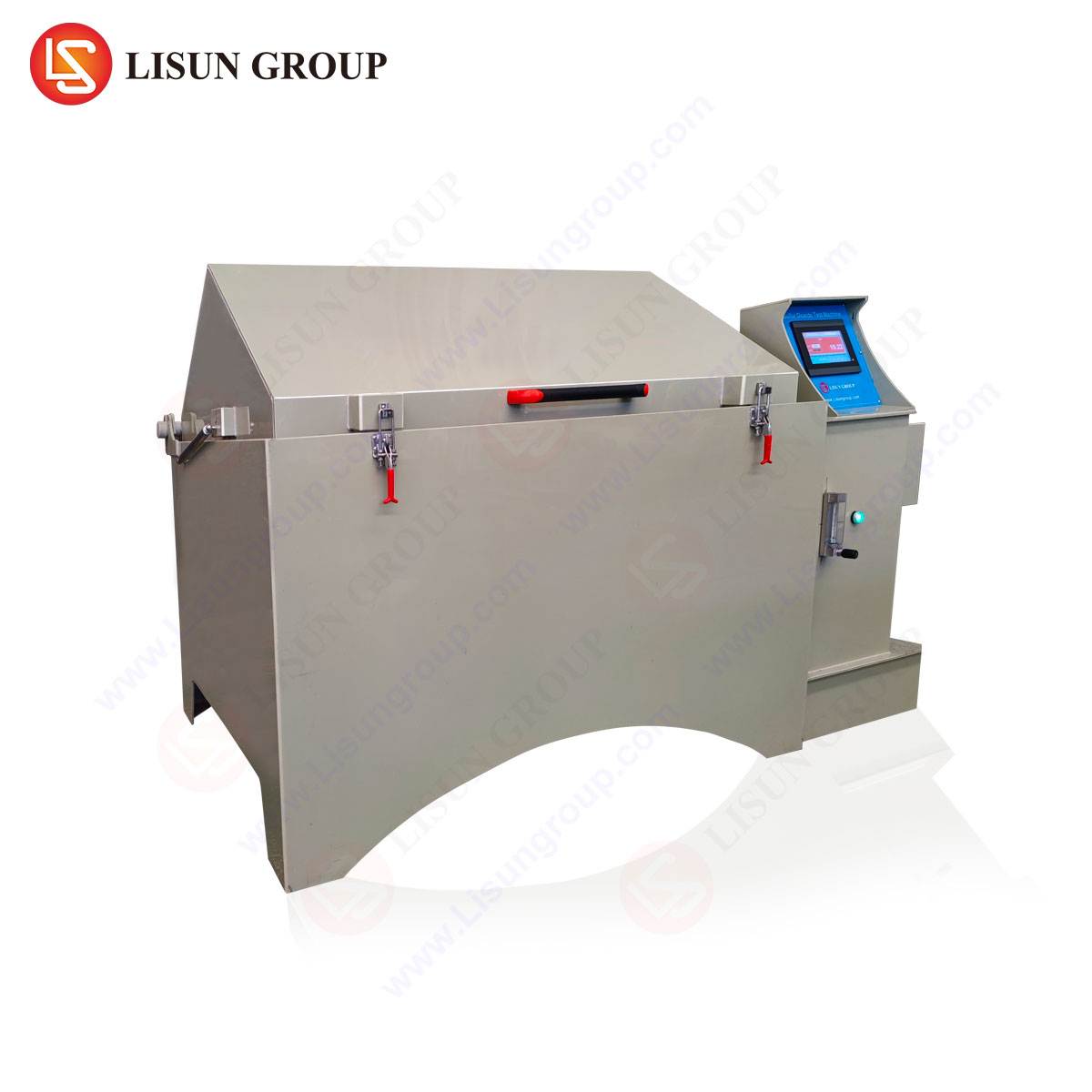
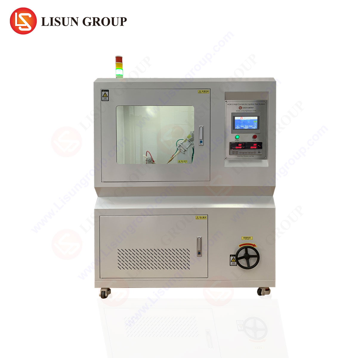
To standardize the assessment of arc ignition resistance, specific test apparatuses are mandated by standards such as IEC 60947-1, IEC 60695-2-20, and UL 1699. The Lisun HCAI-2 High Current Arc Ignition Test System represents a sophisticated implementation of these standardized methodologies, designed to provide reproducible, compliant, and data-rich durability analysis.
The core testing principle involves the generation of a controlled, high-current arc across the surface of a test specimen. The system typically comprises a high-voltage, high-current power supply; programmable current and voltage regulators; a precision electrode assembly (often tungsten rods of specified geometry); a motorized electrode separation mechanism; and an integrated detection system for arc ignition, sustained flaming, and specimen burn-through. The test specimen is mounted on a standardized base, and the electrodes are brought into contact with or positioned near the specimen surface.
A key test sequence is the Arc Ignition Test. Here, a series of arcs are struck across the specimen by separating the electrodes while current is flowing. The severity is defined by specific arc classes based on the open-circuit voltage and short-circuit current of the test circuit. For instance:
- Class 1: 12.5 kV, 10 kA
- Class 2: 12.5 kV, 7.5 kA
- Class 3: 12.5 kV, 5 kA
- Class 4: 12.5 kV, 2.5 kA
The Lisun HCAI-2 system is engineered to accurately generate and control these parameters. Its specifications ensure test integrity:
- Test Voltage: 0.5 kV to 12.5 kV, continuously adjustable.
- Short-Circuit Current: 0.5 kA to 10.0 kA, programmable in accordance with arc classes.
- Arc Duration & Repetition: Programmable arc-on and arc-off times (e.g., 0.1s to 9.9s), with adjustable intervals between arcs.
- Electrode Control: Automated, motor-driven electrode separation with precise speed and distance control.
- Detection Systems: Optical sensors for flame detection, current/voltage monitoring for arc sustainability, and optional high-speed recording for arc behavior analysis.
- Safety Enclosure: Interlocked test chamber with exhaust for pyrolysis byproducts.
The system operates by first establishing the specified short-circuit current. The electrodes are then separated at a controlled rate, drawing an arc. The test evaluates whether the material/component ignites, sustains the arc, or allows the arc to cause a conductive path that persists after the arc is terminated. The number of arcs withstood before failure, or the pass/fail outcome after a standard sequence, quantifies the durability.
Interpreting Test Data for Material and Component Qualification
Raw data from an HCAI-2 test sequence requires analytical interpretation to be actionable. The primary output is often a binary pass/fail against a specific standard’s requirement (e.g., “withstand 15 arcs of Class 3 severity without ignition”). However, more nuanced analysis is possible.
Post-Test Inspection is critical. This involves measuring the length and depth of any erosion tracks, examining the extent of carbonization, and assessing mechanical damage. A material that passes but shows deep, localized pitting may have limited functional life in a real-world application where multiple arc events are possible over time.
Performance Benchmarking involves testing multiple material formulations or component designs under identical conditions. The data can be tabulated for comparative analysis:
| Material/Component | Arc Class Tested | Arcs to Failure | Max. Track Length (mm) | Observations |
|---|---|---|---|---|
| Thermoset Polyester (Grade A) | Class 4 | 28 | 12.5 | Sustained flaming at arc 29. |
| Thermoset Polyester (Grade B) | Class 4 | 15 | 9.8 | No flame, but conductive track formed. |
| Epoxi relleno de cerámica | Class 3 | >30 (No Failure) | 2.1 | Minor surface discoloration only. |
| Molded Switch Housing (Design 1) | Class 2 | 12 | N / A | Arc penetrated housing wall. |
| Molded Switch Housing (Design 2) | Class 2 | >15 (Pass) | N / A | Slight surface charring, no penetration. |
Such data directly guides engineering decisions. For example, the ceramic-filled epoxy demonstrates superior arc resistance suitable for industrial control busbars, while the difference between switch housing designs may relate to wall thickness, material flow during molding, or the presence of flame-retardant additives.
Competitive Advantages of Automated, High-Precision Arc Testing
The transition from manual or semi-automated arc test setups to integrated systems like the HCAI-2 confers significant technical and operational advantages. Repeatability and Reproducibility are paramount in compliance testing; automated electrode movement and parameter control eliminate human variability in arc initiation timing and electrode separation speed.
Enhanced Operator Safety is a critical benefit. The fully interlocked enclosure and automated sequencing minimize exposure to high voltage, UV radiation, and toxic pyrolysis fumes. Integridad de los datos is improved through direct digital recording of voltage, current, and timing, reducing transcription errors and providing a clear audit trail for certification bodies.
Furthermore, the programmability of such systems allows for beyond-compliance research and development. Engineers can create custom test profiles to simulate specific real-world fault scenarios—for instance, simulating the arcing behavior in a cable and wiring system under flexing stress, or testing office equipment power supplies under repetitive inrush current events that may stress connectors. This facilitates proactive durability engineering rather than merely reactive compliance checking.
Integrating Arc Durability Findings into Product Lifecycle Management
The ultimate value of material durability analysis lies in its integration into the broader product development and quality assurance lifecycle. Findings from HCAI-2 testing should feed directly into:
- Material Selection Databases: Creating internal benchmarks for material suppliers.
- Design for Reliability (DfR): Informing minimum clearance/creepage distances, contact geometry, and enclosure design.
- Failure Mode and Effects Analysis (FMEA): Quantifying the risk and severity of arc fault failures.
- Accelerated Life Testing (ALT): Using controlled arcing as one stressor in multi-stress aging protocols.
- Supplier Quality Audits: Requiring component suppliers to provide certified test data from recognized apparatuses.
In sectors like Productos sanitarios y Aerospace, where qualification and documentation are rigorous, this integrated data trail is indispensable for regulatory submissions and airworthiness certifications.
Conclusión
The analysis of material durability against high-current arc ignition is a non-negotiable pillar of modern electrical safety and reliability engineering. It transcends simple pass/fail criteria, offering deep insights into the failure thermodynamics of insulating and conductive materials. As electrical systems become more compact, powerful, and ubiquitous—from consumer electronics to aviation components—the energy density and potential arc severity increase proportionally. Employing precise, standardized, and automated test instrumentation, such as that exemplified by the HCAI-2 test system, provides the empirical foundation necessary to design products that are not only compliant but inherently robust, safe, and durable over their intended service life. This analytical rigor directly mitigates fire risks, reduces field failure rates, and underpins the trust placed in the global electrical infrastructure.
Preguntas más frecuentes (FAQ)
Q1: What is the fundamental difference between the HCAI-2 High Current Arc Ignition Test and a Comparative Tracking Index (CTI) test?
A1: While both assess surface degradation, the CTI test (per IEC 60112) uses a low-voltage (up to 600V), low-current solution to create electrolytic tracking on a contaminated surface over a long period. It measures the voltage at which tracking occurs. The HCAI-2 test applies a high-voltage (up to 12.5kV), high-current (up to 10kA) arc directly to the material, assessing its resistance to immediate thermal ablation, ignition, and the formation of conductive paths via direct energy injection, simulating a severe fault condition.
Q2: For a manufacturer of automotive relay connectors, which Arc Class should typically be referenced for testing?
A2: The specific class is dictated by the applicable automotive standard (e.g., LV214, ISO 8820). However, it typically depends on the circuit’s operating voltage and prospective fault current. For a 12V/24V system with a high prospective fault current from the battery, testing at Class 3 or Class 4 may be required to ensure the connector housing and insulating barriers can withstand an arc from a loose or vibrating terminal without sustaining ignition or creating a sustained conductive path.
Q3: Can the HCAI-2 system test complete assembled products, or only material samples?
A3: It is designed for both. Standard material testing uses molded plaques per specified dimensions. Crucially, it can also test end products like switches, sockets, circuit breakers, or enclosed components. The electrodes are applied to critical points on the product (e.g., across open contacts, from a live part to an accessible metal part), assessing the real-world performance of the entire assembly, including air gaps, molding seams, and material interfaces.
Q4: How are the optical flame detection sensors calibrated, and what constitutes a “failure” by ignition?
A4: The sensors are calibrated to a specific sensitivity threshold to distinguish the sustained flame from the transient arc glow. A failure is typically defined as the specimen supporting a flame that persists for longer than a specified duration (e.g., 30 seconds) after the arc current is cut off, as per standards like IEC 60947-1. The system automatically logs the timing and duration of any flame event exceeding this threshold.
Q5: In the context of failure analysis, how can HCAI-2 testing be used on a component that failed in the field?
A5: The system can be used for forensic reconstruction. If a suspected arc fault caused a field failure, exemplar components or the failed component’s material can be tested under controlled conditions. By correlating the test-induced damage (track patterns, erosion depth) with the field failure artifact, engineers can confirm the failure mode, estimate the energy involved, and validate corrective design or material changes.