


Advancements in High-Current Fault Simulation for Enhanced Product Safety and Reliability
The relentless evolution of electrical and electronic equipment across diverse sectors necessitates a parallel advancement in the methodologies employed to validate their safety and operational integrity. Among the most critical failure modes requiring rigorous assessment is the high-current arc fault—a catastrophic event characterized by the uncontrolled flow of substantial electrical current through an ionized air path. Such events pose severe risks, including fire initiation, component vaporization, and systemic functional collapse. Consequently, the development and implementation of sophisticated testing solutions capable of accurately simulating these extreme conditions are paramount for manufacturers, certification bodies, and research institutions. This article delineates the technical imperatives, standardized frameworks, and practical implementations of advanced high-current arc ignition testing, with a specific examination of its application across multiple industrial domains.
The Electrophysical Basis of High-Current Arc Phenomena
An electrical arc constitutes a sustained plasma discharge resulting from the breakdown of a dielectric medium, typically air, under a sufficiently high electric field. While low-energy arcs are often associated with tracking or insulation degradation, high-current arcs represent a distinct and more hazardous regime. They are initiated by faults such as direct short circuits, loose connections, or the failure of current-carrying components, leading to current magnitudes that can exceed thousands of amperes. The energy release, governed by the integral of current squared over time (I²t), is immense, generating localized temperatures that can surpass 10,000 Kelvin. This thermal plasma column causes rapid ablation of contact materials, ionization of surrounding gases, and can act as a highly effective ignition source for adjacent flammable materials.
The simulation of this phenomenon in a controlled laboratory environment requires apparatus capable of delivering precisely regulated high-current pulses while monitoring key parameters such as peak current, arc voltage, duration, and total transferred energy. The test’s objective is not merely to observe failure but to quantitatively evaluate a component’s or assembly’s ability to contain, extinguish, or safely manage the arc energy without propagating fire or causing unacceptable damage. This forms the foundational principle behind standardized tests like those defined in IEC 60947-1, UL 1699, and specific automotive and aerospace directives, which mandate performance thresholds for devices exposed to potential fault conditions.
Architectural Principles of Modern High-Current Arc Test Instrumentation
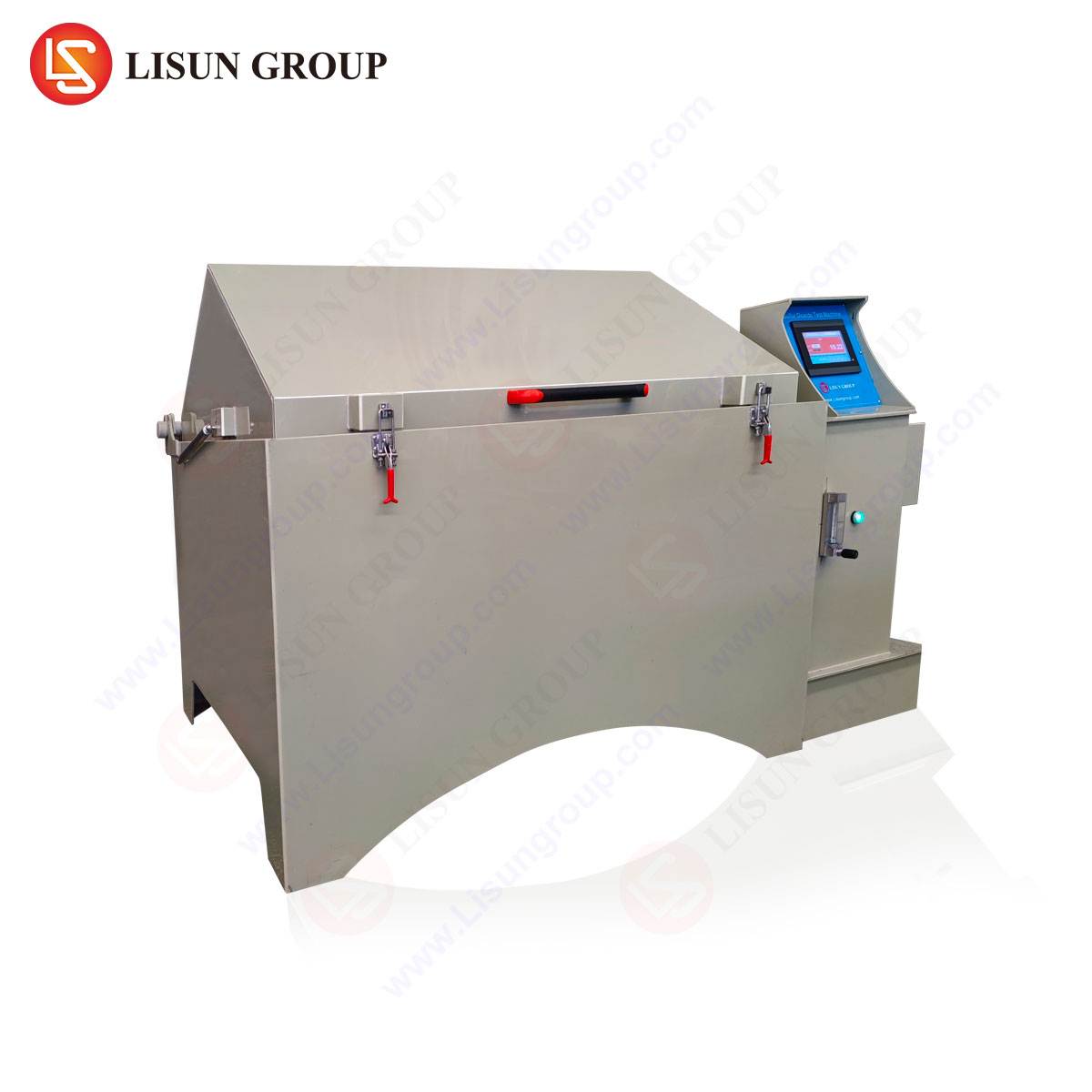
Contemporary high-current arc ignition test systems are engineered to fulfill the dual demands of standardized compliance and investigative research. A sophisticated apparatus must integrate several core subsystems: a high-capacity, low-impedance programmable power supply capable of sourcing the requisite fault current; a precise digital ignition controller to initiate the arc at a predetermined point on the voltage waveform; a robust and safe test chamber with appropriate containment and ventilation; and a high-speed data acquisition unit to capture transient electrical and optical events.
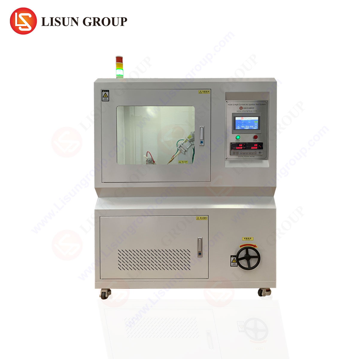
O LISUN HCAI-2 Teste de ignição por arco de alta corrente Sistema exemplifies this integrated architectural approach. Its design centers on generating repeatable, standards-compliant arc faults to assess the ignition risk of insulating materials, the containment capability of enclosures, and the fault tolerance of electrical connections. The system operates on the principle of establishing a prospective fault current between electrodes, which is then initiated via a programmable ignition pulse. Key specifications that define its operational envelope include a test current range extending from 10A to 2,000A, accommodating both branch-level and main supply fault simulations. The open-circuit voltage is adjustable, typically up to 440V AC/DC, to replicate various supply conditions. Crucially, the ignition angle can be controlled across a full 0–360° range, allowing simulation of the most severe fault inception point (e.g., at voltage peak for maximum energy transfer). The inclusion of a high-speed data logger, sampling at rates exceeding 1 MS/s, is essential for capturing the microsecond-scale dynamics of arc establishment, including in-rush current, stable arc voltage, and eventual clearing or extinction.
Table 1: Representative Technical Parameters of a High-Current Arc Test System
| Parâmetro | Typical Specification Range | Primary Influence on Test Outcome |
| :— | :— | :— |
| Corrente de saída | 10 – 2,000 A | Determines the severity of the simulated fault. |
| Open Circuit Voltage | 0 – 440 V AC/DC | Affects arc initiation energy and stability. |
| Ignition Phase Control | 0 – 360°, ±1° resolution | Allows targeting of maximum stress point in AC cycle. |
| Current Duration | Programmable, 1 ms – 10 s | Controls total let-through energy (I²t). |
| Data Acquisition Rate | ≥ 1 MS/s | Enables accurate capture of transient waveforms. |
Cross-Industry Application Paradigms for Arc Fault Testing
The utility of high-current arc testing transcends a single industry, providing critical validation data for any sector where electrical energy is distributed or controlled.
Em Automotive Electronics and Aerospace Components, the migration to higher voltage architectures (e.g., 48V systems, 400V+ EV powertrains) amplifies arc fault risks. Testing battery management system (BMS) connectors, high-voltage contactors, and wiring harnesses under fault conditions ensures they will not ignite surrounding materials in the event of a crash or insulation failure, directly supporting compliance with ISO 6469-3 and AS/EN 9100 series requirements.
Para Electrodomésticos e eletrónica de consumo, the focus is on internal connections, power supply units, and switching components. A loose terminal block in a washing machine or a failed triac in an air conditioner can become an arc source. Testing validates that the internal layout, barrier materials, and enclosure design prevent user-accessible surfaces from becoming hazardous or igniting external combustibles.
Industrial Control Systems and Telecommunications Equipment often reside in environments with dust, vibration, and corrosive atmospheres, which can degrade connections over time. Arc testing of terminal blocks, relay contacts, and power distribution units within control panels (to IEC 61439-2) verifies their robustness, ensuring a single internal fault does not cascade into a panel-wide failure or fire.
Luminárias, particularly high-intensity discharge (HID) or high-power LED drivers, can harbor potential fault points. Testing the mechanical and electrical integrity of lamp holders, wire connections, and ballast housings under high-current fault conditions is essential for safety certification under IEC 60598.
Medical Devices and Office Equipment demand exceptional reliability. An arc fault in an MRI power cabinet or a large-format printer power supply must be contained. Testing here focuses on the flame-retardant properties of internal plastics, the integrity of grounded shields, and the performance of overcurrent protective devices within the equipment itself.
Methodological Implementation and Standards Alignment
Effective testing is not merely the application of current but a methodical process aligned with relevant international standards. A typical test sequence for a component, such as a switch or connector, involves several stages. First, the specimen is mounted within the test chamber according to its intended service configuration. Electrodes are connected to simulate a realistic fault path—for example, across a loosened terminal screw or between adjacent pins of a connector. The test standard (e.g., IEC 60947-1 Annex H) defines the “prospective current,” which the system calibrates by shorting the electrodes with a low-impedance link prior to the actual test.
The critical phase is the controlled ignition. The system charges its energy storage, and upon trigger, applies the full open-circuit voltage while initiating the arc at the specified phase angle. The high-speed acquisition system records the resulting current and voltage waveforms. Post-test analysis evaluates multiple criteria: whether the arc caused sustained flaming of the specimen or a surrounding indicator material (like cheesecloth), the duration of flaming combustion, and the physical extent of damage. A passing result typically requires any flames to self-extinguish within a specified time and not propagate beyond defined limits.
O LISUN HCAI-2 system is explicitly engineered to automate this workflow, ensuring repeatability and traceability. Its software allows for pre-programmed test sequences that automatically set current, voltage, ignition angle, and duration, execute the test, and record all waveform and result data. This reduces operator influence and generates auditable reports for certification agencies like UL, TÜV, or Intertek.
Comparative Advantages in Precision and Diagnostic Capability
The value of an advanced testing system lies in its precision, diagnostic depth, and operational safety. Traditional methods using fixed transformer banks and manual ignition lack the controllability to simulate the precise worst-case fault or to generate consistent, comparable data. A system with programmable ignition angle control, for instance, can repeatedly test at the 90° point (voltage peak) on an AC waveform, ensuring each specimen is subjected to identical initial stress conditions. This is a significant competitive advantage for quality assurance and comparative material studies.
Furthermore, the integration of high-bandwidth data acquisition transforms the test from a pass/fail event into a rich diagnostic tool. By analyzing the captured arc voltage and current waveform, engineers can infer characteristics such as arc stability, electrode erosion rate, and the effective impedance of the plasma channel. This data is invaluable for R&D teams working to improve contact metallurgy, develop more effective arc chutes in circuit breakers, or formulate higher-performance insulating polymers. The ability to correlate specific waveform signatures with observed physical failures accelerates the iterative design process, moving beyond compliance to genuine performance optimization.
Integrating Arc Fault Data into a Comprehensive Safety Engineering Strategy
Ultimately, high-current arc ignition testing should not exist in isolation. Its outputs are most powerful when integrated into a broader product safety and reliability engineering strategy. Data from these tests feed into Failure Modes and Effects Analysis (FMEA), guiding design revisions. They validate simulations performed in computational arc plasma models. They provide empirical evidence for the selection of one component over another in a bill of materials.
For manufacturers across the spectrum from Componentes eléctricos to Aeroespacial e aviação, this integration means building a safety case that is both preventative and mitigative. Preventative design minimizes the probability of a fault occurring through robust connections and derated components. Mitigative design, validated by tests like those performed on the HCAI-2, ensures that if a fault does occur, its consequences are contained, preventing a transition from an electrical fault to a thermal fire event. This holistic approach, underpinned by precise, reliable, and standardized testing, is fundamental to achieving the levels of safety and reliability demanded by modern global markets and regulatory frameworks.
Perguntas frequentes (FAQ)
Q1: How does the controlled ignition phase angle affect the severity of an arc fault test?
The ignition phase angle on an AC waveform directly determines the instantaneous voltage at the moment of fault initiation. Ignition at or near the voltage peak (90° or 270°) applies the maximum available voltage to break down the gap between electrodes, typically resulting in the most energetic and severe arc initiation. Testing at this worst-case angle ensures a conservative safety margin, as it replicates the most stressful possible real-world fault condition.
Q2: What is the significance of the “prospective current” setting in these tests?
Prospective current, also known as available fault current, is the maximum current that would flow if a zero-impedance short circuit were applied at the test point. The test system is calibrated to this value prior to the actual arc test. It represents the theoretical maximum severity of a fault on the specific electrical circuit supplying the equipment under test. Testing to the appropriate prospective current level ensures the component is validated for its intended installation environment, whether a residential branch circuit (lower current) or an industrial distribution panel (very high current).
Q3: Can high-current arc testing be used for both component-level and complete assembly evaluations?
Yes, the methodology is scalable. At the component level, it is used to test individual items like switches, connectors, or terminal blocks. For complete assemblies, such as a control panel, appliance enclosure, or automotive battery box, the test evaluates the interaction of all internal components, wiring, and the enclosure itself when an internal arc is deliberately induced. The pass/fail criteria may differ, often focusing on containment of particles, prevention of door blow-open, and absence of external ignition.
Q4: How are the results of a high-current arc ignition test typically quantified and reported?
Results are both qualitative and quantitative. Qualitative observations include whether flaming occurred, the nature of the flames (e.g., brief sparks vs. sustained combustion), and the physical damage to the specimen. Quantitative data includes the exact peak current and voltage waveforms, arc duration, total energy (calculated from I²t), and the time for any ignited materials to self-extinguish. This data is compiled into a formal test report, often required for safety certification submissions.
Q5: What safety precautions are integral to a system like the HCAI-2 during operation?
Integrated safety is paramount. Systems feature interlocked test chambers that prevent access during energization, reinforced containment to withstand pressure bursts from arc plasma, and forced ventilation to extract combustion byproducts. Electrical safety includes ground-fault protection, emergency stop circuits, and systems that automatically discharge stored energy after a test or upon abort. Operational protocols mandate the use of personal protective equipment (PPE) and strict procedural controls.