


A Comprehensive Guide to IEC 60598-1 Compliance: Ensuring Luminaire Safety Through Mechanical Integrity Testing
The International Electrotechnical Commission’s standard IEC 60598-1, titled “Luminaires – Part 1: General requirements and tests,” constitutes the foundational safety specification for lighting fixtures globally. Its adoption, often mirrored in regional standards like EN 60598-1 in Europe and UL 1598 in North America, establishes a critical framework for mitigating risks associated with electrical, thermal, and mechanical hazards. While electrical insulation and thermal endurance are frequently emphasized, the standard’s provisions for mechanical strength, particularly impact resistance, are equally vital for ensuring product longevity and user safety across diverse applications. This guide provides a detailed examination of the mechanical testing requirements within IEC 60598-1, with a specific focus on the implementation, significance, and validation of impact tests as mandated by Clause 4.13.
Foundational Principles of Mechanical Testing in Luminaire Safety
IEC 60598-1 approaches mechanical safety from a holistic perspective, recognizing that luminaires are subject to various stresses during installation, service, and accidental contact. The standard’s requirements are not merely about structural robustness but are intrinsically linked to maintaining protective insulation, preventing live part exposure, and ensuring that the fixture does not become a source of injury or fire. Mechanical failures can compromise creepage and clearance distances, fracture insulating materials, or displace critical components, thereby precipitating electrical faults. Consequently, the tests prescribed are designed to simulate realistic mechanical insults, verifying that the luminaire’s construction can withstand such events without violating the core safety principles established throughout the standard. The evaluation extends beyond immediate failure, requiring that the sample remains compliant with all relevant safety clauses post-test, including dielectric strength and touch current assessments.
Deciphering the Impact Energy Requirements of Clause 4.13
Clause 4.13, “Mechanical strength,” specifies the impact test as a key validation method. The test is designed to verify the resistance of enclosures and protective covers to impacts that may occur in service. The standard delineates requirements based on the luminaire’s weight and its intended mounting height or accessibility. For luminaires exceeding 0.5 kg, the impact energy is stipulated as 0.7 Nm (Newton-meters) for samples mounted at heights not exceeding 0.3 meters, and 0.35 Nm for those mounted higher, reflecting a reduced likelihood of severe impact. For lighter luminaires (≤ 0.5 kg), a simplified pendulum or spring hammer test applying 0.2 Nm is permitted.
The test apparatus mandated is the spring-operated impact test device, commonly referred to as an “IK tester” in broader mechanical testing parlance, though referenced specifically in IEC 60598-1. This device delivers a reproducible, calibrated impact via a spring-loaded plunger with a hemispherical striker of specified radius. The test requires impacts to be applied to the samples’ most vulnerable points, including transparent covers, after they have been conditioned to their lowest expected operating temperature, typically -15°C ±2°C, to assess material behavior under brittle conditions. A critical pass/fail criterion is that live parts must not become accessible, and the sample must not exhibit cracks or holes that would fail the standard’s dust/water ingress or electric shock protection tests.
Instrumentation for Validated Compliance: The LISUN IK07-10VT IK Test System
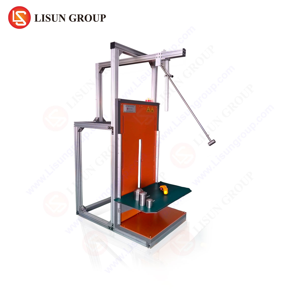
Accurate and reproducible execution of the Clause 4.13 test is contingent upon precise instrumentation. The LISUN IK07-10VT IK Test system is engineered specifically to meet the rigorous demands of this and related impact tests defined in IEC 60068-2-75 and other standards referencing IK codes (IEC 62262). This system transcends basic compliance, offering a integrated solution for validating luminaire mechanical integrity across the required energy spectrum.
The system’s core is a calibrated vertical impact test device capable of delivering impact energies from 0.14 J (IK01) up to 10 J (IK08), fully encompassing the 0.2 J, 0.35 J, and 0.7 J requirements of IEC 60598-1. Its vertical drop design ensures consistent, gravity-assisted impact alignment, eliminating potential angular inconsistencies found in manual spring hammer applications. The IK07-10VT model incorporates a variable height release mechanism and interchangeable impact hammers of varying mass (250g, 500g, 1.75kg), allowing technicians to precisely configure the test parameters per the standard’s formula (E = mgh, where E is energy in Joules, m is mass, g is gravity, and h is drop height).
Key specifications of the LISUN IK07-10VT include a drop height range of 0-1000mm, a high-precision electromagnetic release mechanism to prevent accidental discharge, and a rigid vertical guide column with minimal friction. The system often features an integrated sample mounting table with adjustable clamps and height positioning, crucial for testing larger or irregularly shaped luminaires as intended by the standard. The use of such a system ensures that the impact energy is applied perpendicularly to the test surface, a critical factor for generating valid, auditable test results.
Cross-Industry Implications of Mechanical Integrity Validation
The principles validated by the IK07-10VT system extend far beyond general illumination. The mechanical resilience of enclosures is a universal safety concern across electrotechnical sectors.
- Electrical Components & Industrial Control Systems: Terminal blocks, switchgear enclosures, and PLC housings must resist impacts from tools or falling objects in industrial environments to maintain operator safety and system integrity.
- Automotive Electronics & Aerospace Components: Control units, sensor housings, and interior lighting must withstand vibration and incidental impacts during vehicle operation or maintenance, where failure could have severe consequences.
- Medical Devices & Telecommunications Equipment: Portable diagnostic equipment, bedside monitors, and network enclosures in public spaces require robust construction to endure handling and environmental knocks without functional compromise.
- Household Appliances & Consumer Electronics: The enclosures of kitchen appliances, power supplies, and smart home devices are subject to daily wear and accidental drops, necessitating validated impact resistance to protect users.
In each case, the testing methodology—employing a calibrated, repeatable impact—provides objective data on product durability, directly informing design choices regarding material thickness, polymer selection, and structural reinforcement.
Operational Methodology and Data Integrity in Testing
Implementing the impact test using a system like the LISUN IK07-10VT follows a stringent protocol to guarantee data integrity. The sample is first conditioned in a thermal chamber at the specified low temperature. It is then mounted securely to the test base, ensuring no secondary damping occurs. The appropriate hammer mass is selected and raised to the calculated height to achieve the target impact energy (e.g., for 0.7 Nm/0.7 J, using the 500g hammer, h = E/(mg) = 0.7 / (0.5 9.81) ≈ 0.143m or 143mm). The electromagnetic release ensures the hammer falls freely without initial velocity.
Post-impact, the sample is visually inspected for cracks, fractures, or permanent deformation exceeding permissible limits. Crucially, it is then subjected to relevant verification tests. For luminaires, this typically involves a re-test of dielectric strength (Clause 10.2.2) and an assessment of accessibility to live parts (Section 8). A passing result confirms that the mechanical insult did not degrade the fundamental safety barriers. The primary competitive advantage of a dedicated system like the IK07-10VT lies in its traceability and repeatability. Manual spring hammers are prone to operator influence in angle and velocity. In contrast, the vertical drop system generates a standardized, documentable test condition, reducing inter-operator variability and producing defensible data for compliance certification bodies such as UL, TÜV, or Intertek.
Integrating Impact Test Data into the Product Development Lifecycle
Proactive integration of mechanical testing into the design and quality assurance phases is a hallmark of mature engineering practice. Data derived from systematic impact testing informs material science decisions, such as opting for polycarbonate blends over standard ABS for covers in high-risk applications. It validates finite element analysis (FEA) simulations of stress distribution during impact events. In production, periodic audit testing using the same calibrated equipment ensures that manufacturing processes—such as injection molding parameters, alloy composition, or assembly torque—have not deviated in a way that compromises mechanical strength. For industries like automotive electronics or aerospace, where component failure carries significant liability, this empirical validation is non-negotiable. The LISUN system’s precision makes it suitable not only for final type-test certification but also for these essential R&D and quality control functions, providing a consistent benchmark throughout the product lifecycle.
Conclusão
Compliance with IEC 60598-1 is a multifaceted endeavor where mechanical integrity is inseparable from electrical safety. The impact test specified in Clause 4.13 serves as a critical empirical check on a luminaire’s ability to endure physical shock. Employing a calibrated, vertical-drop impact test system such as the LISUN IK07-10VT IK Test system ensures this assessment is performed with the accuracy, repeatability, and traceability required by international certification schemes. The principles and equipment discussed, while focused on luminaires, find direct parallel in the safety validation of enclosures across the entirety of the electrotechnical industry, from consumer appliances to mission-critical aerospace components. As product ecosystems become more complex and safety expectations escalate, rigorous, instrumented mechanical testing remains an indispensable pillar of responsible design and manufacturing.
Secção FAQ
Q1: Can the LISUN IK07-10VT system be used for testing beyond the specific energy levels called out in IEC 60598-1?
Yes, absolutely. The system is designed to cover the full IK code range from IK01 (0.14 J) to IK08 (10 J) as defined in IEC 62262. While IEC 60598-1 typically requires energies up to 0.7 J, other product standards (e.g., IEC 60950 for IT equipment, IEC 60601-1 for medical devices) or specific customer specifications may require higher impact resistance validation. The IK07-10VT’s adjustable height and interchangeable hammers provide this flexibility.
Q2: How does testing at low temperature affect the results, and is conditioning always necessary?
Low-temperature conditioning, as specified in IEC 60598-1, is essential because many polymeric materials become more brittle and less ductile as temperature decreases. An enclosure that appears robust at room temperature may fracture under a standard impact at -15°C. The test aims to simulate a worst-case environmental scenario. The requirement for conditioning is standard-dependent; IEC 60598-1 explicitly requires it for this impact test, but other standards may specify ambient or elevated temperature testing.
Q3: What is the difference between the “IK test” referenced here and the “pendulum test” sometimes mentioned?
The IK test, codified in IEC 62262, is a comprehensive rating for degrees of protection provided by enclosures against external mechanical impacts. It utilizes various methods, including the vertical drop test (as with the IK07-10VT) for higher energies. The “pendulum test” is a specific type of impact test, often used for lower energies or in older versions of some standards. The spring-operated hammer described in IEC 60598-1 is a third, distinct device. The LISUN system aligns with the modern, vertically-applied impact method, which offers superior reproducibility for the energy levels in question.
Q4: After an impact test failure, what are the typical design remediation steps?
Failure analysis typically leads to one or more design modifications: increasing wall thickness in the impacted area, switching to a material with higher impact strength or a better low-temperature ductility rating (e.g., moving from a generic thermoplastic to an impact-modified grade), adding internal ribbing or structural supports behind the impact face, or redesigning the shape to better distribute and absorb impact energy. The test system is then used to iteratively validate the effectiveness of these changes.
Q5: Is calibration of the impact test system required, and if so, how is it performed?
Yes, regular calibration is mandatory for maintaining test validity and laboratory accreditation (e.g., ISO/IEC 17025). Calibration involves verifying the drop height scale accuracy using a calibrated height gauge and confirming the mass of the impact hammers with precision scales. Some laboratories may also perform periodic verification checks using a calibrated force sensor or accelerometer mounted on the anvil to confirm the actual impact energy delivered. The system’s design facilitates these calibration procedures.